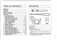
TABLE OF CONTENTS IMPORTANT . Aerialist FOREWORD .. CAUTIONS OPERATING NOTES TABLE OF CONTENTS . UNPACKING ...l « BASIC OPERATION . PANEL DESCRIPTION . CHARGING A BATTERY PACK 11-12 . /ACCESSORY INFORMATION .. 13-14 1518 . REPEATER OPERATION 19-20 . MODE ARRANGEMENT i CALL CHANNEL MEMORY OPERATION 10. SCAN OPERATION i 11 PROBITY WATCH SETTING A FREQUENCY MDT MEMORY OPERATION BEEP AND POWER SAVER 34 14. CLOCK AND TIMER OPERATION . 35-40 15.
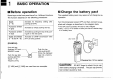
. ] BASIC OPERATION il Before operation Some keys on the front panel have 3 or 4 different functions. The function depends on the following procedures; Digits Activated for frequency settling alter 1~0) pushing [ LENT Functions written gray Activated by simply pushing the key. Functions written: | Activated by pushing the key while pushiness ing {F] on the side panel. Digits and letters |Activated: for DIM transmission: while {1 ~0 and A=D) 1 IPTT]i5 being pushed.
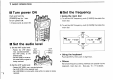
Reset the transceiver It the display shows erroneous information when first applying power, the transceiver may require: CPU resetting. 1) While pushing the [F], [U MAIN] and CLR] keys, push [POWER] for 1sec.toturn power ON. 2) The CPU is reset and the function display shows as follows: * U S Aversion 146,07, 440.00 MHz » Asia version MHz ¢ Other versions 145.00, 430.00 MHz f@ Connect the supplied antenna Insert the supplied antenna into the antenna connector and twist the antenna as shown in the diagram.
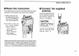
1 BASIC OPERATION Turn power ON Push and hold the [POWER] key for 1 sec. to turn power ON; + A beep sounds at power ON. )ei A Set the audio level 1} Set the VHE audio level: Rotate the VHF [saL] YHE ot max: counterclockwise. oLl ! . Set VHE [VOL] 10 the [SQH desired level. Set VHFISQL] to mute audio noise while signalization being received. 2) Set the UHF audio level: Rotate UHF [SQL] max. counterclockwise. = Set UHF [VOL] to'the desired level.
H When receiving a signal The transceiver can receive a VHF and a UHF signal simultaneously. When receiving, the transceiver functions as follows: 1. Emits the received signal(s) from the speaker. 2. Indicates the relative signal strength on the received band Si indicator on the function display. M Bod M08 spssasussomm 3 3 | When receiving a signal on the VHE band. NOTE: When a [SQL] control is set too “tight”! {extremely clockwise), squelch may not open for weak signals.
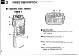
e Bl 2 PANEL DESCRIPTION B Top and side panels seventieth Bat e 6L (& 000 © MAIN DIAL [DIAL] Sets an operating frequency, a memory channel, contents in SET mode, efc. © UHF VOLUME CONTROL [VOL] (p. 3) Adjusts the UHF band audio level. © UHF SQUELCH CONTROL {SQL] (p. 3) Varies the squelch threshold point for UHE band noise mute, © VHF VOLUME CONTROL [VOL] (p. §) Adjusts the VHF band audio level.
© VHF SQUELCH CONTROL [SOL] (p. 3) Varies: the squelch: threshold point for VHF band nose mute. © ANTENNA CONNECTOR (p. 2) Connects the supplied flexible antenna. @ FUNCTION SWITCH [F] (pgs. 7. B) While pushing [F], all switches are set for secondary function ‘use. (Functions written in blue are 'secondary functions.) *In VFO mode, the dial select function is activated. The dial Select function changes the memory channel or changes the frequency in 100 kHz or 1 MHz steps by rotating the main dial.
2 PANEL DESCRIPTION M Front panel VAIN GAMIN. Ve LIGHT @ CALL MG-Y TRAVERSE L o uon WOMB TR SAL. MASK: 60® O®G P STEM b Arc sai, CLAMBER CLOCK/AG OVERCLOCK Dharma OBOE ANISE pros; ©) G 5 1080 © KEY FUNCTION WHILE PUSHING [F] V. MAIN @ Selects the VHE band as the MAIN band. | Activates the transceiver for the VHF band o3 only. {p: 18) Von THAN Selects the UHE band as the MAIN band |Activates the transceiver for the Headband -3y | Monty. p.
PANEL DESCRIPTION 2 KEY FUNCTION WHILE PUSHING [F] AFTER PUSHING [ENT] gnaw | Selects VEO or MEMORY mode. Wiles the VFO contents into the memory Chan: nel or call channel when pushed and held. {pgs: 23, 25) Used only for numeral put: Na secondary function: gkt Turns ON the display lighting for 5 sec: Turns ON the display lighting continuously: caveat. 1 Calls up the call channel. {p. 23) | Transfers:the contents in the selected memory or call channel into the VFO. {p.
2 PANEL DESCRIPTION B Function display o mmo | o i 7ol Lot HEREON YOO e OW EMBROIDERER: LO! IS0 ! ;3’ ;.i' MAIN BAND INDICATORS (p. 3) “MAIN'’ appears above the band, either VHE or UHF, selected as the main band 1o be controlled. © TIMER INDICATOR (p. 39) Appears when the power-off timer is in use. © VHF BAND FREQUENCY READOUT Shows the VHF band frequency, SET mode contents or time. » The decimal point of the frequency flashes while scanning. © PTT LOCK INDICATOR (p.
© S/RF INDICATORS (pgs. 4, 18) Show the relative signal strength in receiving; show the output power selection in transmitting. © MEMORY CHANNEL READOUTS (pgs. 24 ~26) Show the selected memory channel number. o @B appears when MEMORY mode is selected. . appears when the selected memory channel is seats a skip channel. @ TONE SQUELCH INDICATORS (pgs. 19, 46) These indicators appear when an optional® UT-63 TONE SQUELCH UNIT is in use. «“T" appears when the sub audible tone encoder is used.
. 3 CHARGING A BATTERY PACK * Using supplied wall charger Connect the supplied wall charger to the [DC12.5V] jack: DC12.5V] { Supplied wail IG-W2AE: charger Charging time: 15 hrs. (approx.) * Using an optional BC-72 Insert the battery pack into the char: ing slot of the BC-72. BP-90 ‘BATTERY CASE cannot be charged using the BF-72 even when Nice batteries are installed, Connect the wall charger supplied with the BC:72. BC-72 (optional} Charging time: 13 hrs. (approx.
CHARGING A BATTERY PACK 3 ¢ Charging without the transceiver To charge the battery pack separately from the transceiver, AD-20 is available from: com. AD-20 (optional) The same chargers as described in “Optional chargers and cables’ can be used. The BP:85 cannot be charged via an optional AD-20. Charging time is 15 hrs. (approx.) * Charging notes *NEVER attempt to charge dry cell batteries with the BP-90. * Connect one charger as described at left. . NEVER connect two or more chargers at the same time.
— Bl 4 ACCESSORY INFORMATION * Battery pack removal Push the battery pack release button upwards, then slide the battery pack to the right with the transceiver facing you. To attach the battery pack, insert it until hearing a click: * Battery case Some versions come with the BP-90 BATTERY CASE instead of a battery pack. To install dry-cell or Ni Cd batteries, open the battery case as shown in the diagram below. 1., Pushkin the bottom part of the battery case 1o open-it. 2.
ACCESSORY INFORMATION 4 * Hand strap The hand strap is convenient for carrying the transceiver. Almach the hand strap as shown in the diagram below: insertions the hand strap using & pointed instrument such as a mechanical pencil: 2. Pu tone end of the hand strap through the other end’s loop. &N 3. Pull the: hand strap to tighten: the knot. * Operating with an optional cable The transceiver can operate with an external DC power source (6~ 16.V.DC, 2 A) through the [DC12.5V] jack.
5 MW Pr-operation note VFO MODE When the transceiver is not in VFO mode, frequency setting is impossible. Push [(1) VIM] or {@ CALL] to select VEQ: mode. » Mode: information :is described on p. 21. MEMORY MODE MY n VEO MODE MED L WHEEL 3{} g,s' Frequency cannot be set: yynnn ot e F beset Sy frequency can Depending on CALL CHANNEL 1he previous mode: LOCK FUNCTION When the lock function is activated, the main dial and keyboard will not function. Use the lock function to prevent accidental frequency changing.
SETTING A FREQUENCY 5 B Using numeral keys 1) Push [V MAIN] or [U MAIN] to select the desired band. 3} Push 4 appropriate digit keys 1o input & frequency. «When d wrong digit is input, push [68 CLR] to clear the input, 2) Push [ ENT] to activate the keyboard for numeral input. then start again from step 2. a5 o0 are acceptable forbid kHz digits; 12" or 7 are also acceptable depending on the 10 kHz digit. [EXAMPLE] Set the frequency to 148520 MHz. This dot appears VAIN when: frequency.
17 5 SETTING A FREQUENCY H Setting a tuning step The main dial or the A7V keys change the frequency in step increments. Different tuning steps can be specified for the VHF and UHF band. B Setting a dial select step In VEO mode, while pushing the [F] key, the main dial changes the frequency in 100 Hz or'1 MHz increments or changes the memory channel according to the select step increment; The display shows the 26.kHz lining sleep. .55 M5.00 “7' . 1 MHz — | 100 KHz The selected digit lashes.
B One band indication When using the IC-W2A/E as a single band transceiver, one band indication can be performed. At this teems; the internal circuits of the unused band are also deactivated. oo Y.MAN "{5 Fiat o @ Lully von 0 maw 1 =-{3 Y4000 o 30 1) While pushing [F], push [V MAIN] or [U MAIN] to hide the display of the unused band. 2) Push [V MAIN] or [U MAIN] to indicate the display of the band in use. One band indication conserves battery power.
I Bl 6 REPEATER OPERATION 18 M General description A repeater amplifies the received signal and transmits it with a different frequency. When using a repeater, the transmit frequency is therefore, shifted from the receive frequency by the offset frequency. 1} Push [V MAIN or [ MAIN] 1o select the desired operating band. 2) Set the receive frequency using the main dial or the keyboard. 3) While pushing [F], push [BUILDUP] to select —duplex and push it d@gain for +duplex.
N Offset frequency The offset frequency can be separately set on the UHF and VHF bands. wne SET MODE REPEATER OPERATION 6 B Sub audible tone .. superwomen frequency The sub audible tone frequency can be set separately on the VHF and UHF bands. The: display shows: the offset frequency: for 600 kHz (D6 MHz) inches VHE bend: 60 YWMEGE oy i MAIN The display shows 151 gg 5 m 1he B85 Hz subaqua: ar 3{;‘ edible tong frequent: oy in the VHE band. 1) MAIN] or [U MAIN] 1o select the desired band.
e Bl / MODE ARRANGEMENT The transceiver has 5 different modes and call channels for versatile, multi-function operations. Bl Mode types VFO MODE (p. 15) Used for normal operations over the entire VHF CLOCK MODE (p 35) Sad for sifting the clock time, power-on time, and and UHE bands. auto: power-off time. { 1 15T TAT 171 MEMORY MODE (p. 24) Used for operating the | | MDT MEMORY MODE (p. 33) Used for programming transceiver using memory MDT codes: 4 DEFEAT channel contents. Each memory channels are : .
M Mode arrangement chart MODE ARRANGEMENT 7 Although the following chart refers only to the VHF band. the transceiver has the same modes in the UHF band. VFO MODE Ser EIl MODE [ Q‘*‘ t"!fi L L CHEERER o Sub audible tone :?n Sg L'Enfant T frequency e = BALLY 020 ¢ : ) MYOPICALLY ! i F01 i (optional. for version) Offset frequency ALy w9D8D MAD 44000 COMBS Y4a0 L s CALL Sean resume — | ! tonsil MEMORY MODE =« 85 GALL CHANNEL ‘climes cmssp\\ Clotting Scan skip friction i il on WEB G o —— DIME MEMORY MODE .
23 . S CALL CHANNEL H Calling up the call channel A one-touch access call channel is provided on each band and is separate from the memory channels. Use the call channel for your most-often-used frequency. B Programming a call channel Call channels can be programmed with not only an opera: ing frequency but also a duplex function and independent offset frequency. CALMLY @ o MELT H3N00 MCLEOD WHIG ViV @) tEn RO YHl gu MED Push [V.
. MEMORY OPERATION O NN B Selecting a memory channel The transceiver has 30 memory channels on each: band for. 1} Push [0 VIM] to select MEMORY mode. storage of confused frequencies: 2} Rotate the main dial to select the desired memory channel. When first applying power or after resetting, memory Chan* Only the memory channels which have been programmed with lens 11 ~30 are masked, < contents wife appear. » Pushing [ SCAN] or [ 7/SCAN] also selects memory channels. Whi the dial select step is set as !he.
9 MEMORY OPERATION B Programming a memory channel 1) Select the memory channel to be programmed: Push [V MAIN] or [U MAIN] 1o select the desired band. = Push (D VM| to select MEMORY mode. (‘M apparatus. Rotate the main dial to select the desired memory channel. = To select blank channels, rotate the main dial while pushing [E]. 2) Set the desired frequency in VFO mode; Push {(1) VIM] to select VFO mode. = Set the desired frequency to be programmed into the memory: channel.
B Transferring memory contents The function copies and transfers the displayed memory contents into the VFO. This function is useful for searching for signals around the memorized frequency. MEMORY OPERATION 9 B Masking memory contents Unwanted memory channels can be masked (hidden). A masked memory channel cannot be selected for normal use. The contents of the masked memory, however, can be recalled by the following procedure. CALL ME 4900 .
T Bl 10 SCAN OPERATION . Scan t . Each band has 4 scan types and 2 resume conditions: are yeps available to suit your needs. Scans on both bands can be simultaneously. » Full scan Repeatedly scans all frequent | * Programmed Repeatedly scans between two ices over the entire selected scan user-programmed frequencies. Bar ' sand band. i MG?‘ S ® See p. 29 for scan edge program!” "« The frequency skip function can ’““i i i Ming. The frequency skip functor SR be used: Sean 2 son can be used.
B Scan operation SCAN OPERATION 10 Head the following table horizontally for each type of scan: procedures in (1), and apply to all scan types. SCAN TYPE| (1) PER-OPERATION 1 PER-OPERATION 2 (@ SCAN START | (SCAN RESUME CONDITION CANOEIST STOP Push “and: hold FULL Push ' VIM] " ‘to | FRANCISCAN] or SCAN select VFO mode. [VI SCAN] for 1 B 1) Program the scan PRO) Push [V MAIN] o [U edge frequencies. , *» Scan resumes 5 sec. after RAMMED MAIN] ‘to select the .29 While pushing {F], receiving a signaler 2 sec.
10 SCAN OPERATION B Programmed scan edges Programmed scan edges can be programmed in the same way as memory writing. Memory channels !'PA" and 'PB” are available for programmed scan edge programming. 1) Push [V MAIN] or [U MAIN] to select the desired band. 2) Select the scan edge memory channel “PA" or 'PB: = Push [(D VIM] to select MEMORY mode. ('M" appears). < Rotate the main dial to select the memory ¢channel “PA” or 3} Set the desired edge frequency in VFO mode: Bush [(1) VIM] to select VEO mode.
SCAN OPERATION 10 H Frequency skip function s Programming a skip frequency * Frequency skip function . SET MODE Frequencies can be skipped when the programmed scan or ON/OFF the full scan is in the pause condition. Memory channels 80~ 11 program skip frequencies in sequence. NERD MIND L SO 43nnn an MUGGING 1. | oFF LERNER Neg E Cai Hon scan pauses. Appears at the moment <‘>f programming. Skip function ON Skip: function OFF 1) Tums ON the frequency skip function; 1) Enter.
10 SCAN OPERATION B Skip channel setting Memory channels can be specified to be skipped for memory skip scan. These skip channels are also skipped during priority watch (memory scan watch) and the frequencies of the channels are skipped during full or programmed scan. B Scan resume s SET MODE condition The resume condition can be selected as a pause or timer scan. | The resume condition is nat only used for scan but also for priority watch.
PRIORITY WATCH 11 W B Priority watch types M Priority watch operation 1} Set the squelch to the threshold point. * When the squelch is tight. priority watch might not stolon 3 ¢ Memory channel while operating in a VFO watch frequency, priority watch weak signal checks the selected memory channel every 5 2) Push [V MAIN] or [U MAIN] 1o select the desired band. VEQ Memory sec. Requisition LS S When the selected memory.
B Programming a MDT code The transceiver has 4 DEFEAT memory channels for storage of often-used MDT codes digits. . Only the VHF band can be used for programming. 1) Push [V MAIN] 1o select the VHE band. 2) While pushing [F]. push [DTMF/DTME M] to enter DEFEAT MEMORY mode. 3) Rotate the main dial to select the desired MDT memory channel. 4) While pushing [F], push SET] 1o set the transceiver in the MDT programming condition. « Previously programmed digits ‘are erased.
] BEEP AND POWER SAVER 13 Nl B Beep tone The transceiver emits a beep tone each time 3 switch s pushed. For silent aeration, the beep tone can be turned OFF. OPERATION While pushing [F], push [BEEP] to turn OFF and ON the beep. NOTE Even: if:the beep is OFF, the transceiver emits a beep tone for the pager function and an optional” pocket beep function. Built-in to' the U.S A version. M Display lighting The display lighting has 4 5 sec. timer for night operation.
e Bl 14 CLOCK AND TIMER OPERATION B Cutoff function ‘The transceiver automatically turns OFF afire a selected period in: which no switch is pushed. * Selecting auto-off periods i1 qufl 1 u WL The display shows an HE autopilot time period of 30 min. Il Clock mode The transceiver is equipped with a clock for operating the power-on and: power-off timers: When only the VHF band is selected as the main band, clock and timer settings are available. Both the: VHF and UHF bands have a clock display.
H Clock operation * Setting time Only the VHF band can be used for clock setting. 1) Enter CLOCK mode: Push [V MAIN] to select the VHE band. Push () CLOCK] to access CLOCK mode: 2) Set the time: ~ While pushing [F], push {8} SET] to set the transceiver in the time setting condition: Rotate the main dial 1o et the hour. < Push [ A/SCAN] or [TOSCANINI; then rotate the main dial 1o sef the minute: Whine a wing time Is set, push [& CLR] and begin this procedure again: Push [@ ENT] to enter the time.
14 CLOCK AND TIMER OPERATION B Power-on timer The transceiver has a power-on timer to fit your schedule and conserve battery power. ¢ Setting power-on time 137 delft :Enter CLOCK mode: = Push [V:MAIN] to select the VHE band. + Push [(0) CLOCK] 1o access CLOCK mode. 2) Select the power-on display; Push [A/SCAN] 1o select the display as shown above.
39 14 CLOCK AND TIMER OPERATION B Power-off timer The transceiver has a power-off timer separate from the auto off function to turn power OFF at the preset time. ¢ Setting power-off time mno c33g 43548 o ! 1) Enter CLOCK ‘mode: ~Push [V MAIN] 1o select the VHF band. = Push CLOCK] to access CLOCK mode. 2) Select the power-off display: = Push [w/SCAN] to select the display as shown above.
CLOCK AND TIMER OPERATION 14 [EXAMPLE Set the power-off time for 12:40. ¥ MAIN Y OR ®F+ ENTITLE CLOCKED oA MASK O & an fnn [ © 680 43500 1238 43708 Louisianan TB CAN PECAN 500 43700 1990 ¥3n00 1200: ¥3100 1Y 43700 Vi hen the set }é time of 1240 o Gites; 4308 4608 43700 M504 43464 Power is turned OFF.
] B 15 PAGER AND CODE SQUELCH B General description * Pager function The pager function is a selective calling system that allows yau to contact a specified station or all stations in your group. To use the pager function in your group, all stations need the pager function. The pager function informs another station with your 1D code which is determined in your:group. : The ID code appears on the other station’s display and is stored there for easy answer back.
W Code programming + Before programming Before operating the pager function; the {following are necessary for determining your group. < [0 code of each transceiver and the group code in your group: < Specification of “'with code squelch’ or 'without code squelch’ for communication after contact: + Channel assignment 12 or Code memory | “'Receive accept’’ or group code channel ‘Receive inhibit” Your 1D code. co ‘Receive ‘accept’’ only o " Receive: inhibit'" should ¢ Ci~Cs be programmed in each channel.
15 PAGER AND CODE SQUELCH B Pager operation » Calling a specific station 1) Push [V MAIN or [U MAIN] to select the desired band. * The pager function cannot be turned ON simultaneously in the VHE and UHF bands. 2) Push [CUPRIC SQL] to turn the pager function ON. s 'PGH! appears. 3) Select the desired code memory channel to be used as & transmit code: = While pushing {F]; push [SCOUNDREL Notate ‘the tuning control to select the chandler. = Push the selected band switch -{V. MAIN] or. [U. MAIN}; to.
PAGER AND CODE SQUELCH 15 B Code squelch operation PERSONAL CALL When you receive a call with your 1D code and received 1D code s 1117 the display at right appears. PAR SO CORP SAL: POI SQL COVE. CODE. ACED: fn h T MED Y3040 |05 43708 \Bn dinned oot GROUP CALL When you receive a call with the group code of YB" and you have programmed ‘555" int code channel (C5, the display at right appears. ERROR INFORMATION When the transceiver receives an incomplete signal, appears.
T B 16 POCKET BEEP AND TONE SQUELCH 3 B UT-63 installation The UT-63 is already installed in:the 1G-W2A U.5.A version, For other versions, an optional UT-63 mus! be purchased > separately. 1} Turn power OFF then remove the-battery pack from the transceiver: 2) Unscrew 5 screws from the rear of the transceiver, 3) Unscrew 2 screws from the side of the transceiver. 4j Remove the rear panel. 5). Bull ‘out: the terminal board. 6): Install and plug the UT-63 as shown in the diagram at right. 7).
M Pocket beep The pocket beep function alerts you for approx. 30 seg. with beep tones and a flashing on the display when you receive a call including the same sub audible tone as that reprogrammed. The pocket: beep cannot be used in combination with the pager or code squelch. 1) Program the sub audible tone frequency in SET made, « See p. 20 for programming details. 2) Push [BIT/P B/T SQL] several times until appears on the function display.
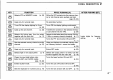
s B 17 TROUBLESHOOTING GUIDE PROBLEM POSSIBLE CASE SOLUTION HEF. * NG power comes on. » The battery pack is employ. » Charge the battery pack of place new dry cell. | p. 11 batteries in the battery case. * Poor plug connection of the external DG pow: | « Check the connector or remove the cable. or cable. « Beeps sound and the power » The bailey pack is empty. » Detach the battery peck-and charge the 1-p. 11 cannot be turned OFF. battery pack or place rise dry cell batteries in the battery case.
. SPECIFICATIONS 18 HEE overage: . Dimensionless weight (Projections not included) FREQUENCY COVERAGE VERSION DIMENSIONS WEIGHT BATTERY PACK] VERSION Tx/Bx IX-WaA S4(W) x 170(H) x 36(D) mime 680G VHF UHe U.S.A 2AW)x 6.7H) x 1AD) i | 125 P84 Woad | Transmit 144 148 440450 Wen IC-W2A 54(W) x 135(H) x 36(D) mm| 400 g 186~ 174 440 450 (Australia) | 210W) 5.30H) x Tad Yin | 141 oz BP-82 (Australia) | and Rx 144~ 148 430440 WIGWAG £404) x 45TH) x 86D) mm| 450 gBP.