!IC-F15_F25.qxd 04.8.
!IC-F15_F25.qxd 04.8.6 5:38 PM Page i (1,1) FOREWORD PRECAUTION READ ALL INSTRUCTIONS carefully and completely before R WARNING! NEVER hold the transceiver so that the antenna is very close to, or touching exposed parts of the body, especially the face or eyes, while transmitting. The transceiver will perform best if the microphone is 5 to 10 cm away from the lips and the transceiver is vertical. R WARNING! NEVER operate the transceiver with a headset or other audio accessories at high volume levels.
!IC-F15_F25.qxd 04.8.
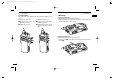
!IC-F15_F25.qxd 04.8.6 5:38 PM 1 Page 2 (1,1) ACCESSORIES ACCESSORIES 1 ■ Accessory attachments 1 D Flexible antenna ï Battery pack Connect the supplied flexible antenna to the antenna connector. To attach the battery pack: Slide the battery pack on the back of the transceiver in the direction of the arrow (q), then lock it with the battery release button. CAUTION: • NEVER HOLD by the antenna when carrying the transceiver. • Transmitting without an antenna may damage the transceiver.
!IC-F15_F25.qxd 04.8.6 5:38 PM 1 Page 4 (1,1) ACCESSORIES ACCESSORIES 1 ï Jack cover D Belt clip Attach the jack cover when the optional speaker-microphone is not used. To attach the jack cover: To detach the jack cover: q Attach the jack cover to the q Unscrew the screws with a [SP MIC] connector. phillips screwdriver. w Detach the jack cover for the w Tighten the screws. speaker-microphone connection. To attach the belt clip: q Release the battery pack if it is attached.
!IC-F15_F25.qxd 04.8.6 5:38 PM 2 Page 6 (1,1) PANEL DESCRIPTION PANEL DESCRIPTION 2 ■ Front, top and side panels q IC-F15S/F25S i IC-F15/F25 w e LED INDICATOR (p. 8) ➥ Lights red while transmitting. ➥ Lights green while receiving a signal, or when the squelch is open. ➥ Lights/blinks orange when the matched 2/5-tone code is received, according to the pre-programming. r SPEAKER-MICROPHONE CONNECTOR [SP MIC] Connects the optional speaker-microphone. (p.
!IC-F15_F25.qxd 04.8.6 5:38 PM 2 Page 8 (1,1) PANEL DESCRIPTION PANEL DESCRIPTION ‘ LED indicator ‘ Programmable function keys The LED indicator indicates several information as follows; (Ref.; R=Red, G=Green, O=Orange) The following functions can be assigned to [Upper] and [Lower] programmable function keys. Consult your Icom dealer or system operator for details concerning your transceivers programming.
!IC-F15_F25.qxd 04.8.6 5:38 PM 2 Page 10 (1,1) PANEL DESCRIPTION MONITOR KEY ➥ Mute and release the CTCSS (DTCS) or 2-tone squelch mute. Open any squelch/deactivate any mute while pushing this key. (LMR operation only) ➥ Activates one of (or two of) the following functions on each channel independently: (PMR operation only) • Push and hold to un-mute the channel (audio is emitted; ‘Audible’ condition). • Push to mute the channel (sets to ‘Inaudible’ only).
!IC-F15_F25.qxd 04.8.6 5:38 PM 3 Page 12 (1,1) CONVENTIONAL OPERATION CONVENTIONAL OPERATION 3 ■ Turning power ON ■ Call procedure ➥ Rotate [VOL] to turn power ON. When your system employs tone signalling (excluding CTCSS and DTCS), the call procedure may be necessary prior to voice transmission. The tone signalling employed may be a selective calling system which allows you to call specific station(s) only and prevent unwanted stations from contacting you.
!IC-F15_F25.qxd 04.8.6 5:38 PM 3 Page 14 (1,1) CONVENTIONAL OPERATION CONVENTIONAL OPERATION 3 ■ Receiving and transmitting NOTE: Transmitting without an antenna may damage the transceiver. See p. 2 for antenna attachment. Receiving: q Rotate [VOL] to turn power ON. w Toggle [CHANNEL SWITCH] (IC-F15S/F25S), rotate [CHANNEL SELECTOR] (IC-F15/F25) or push one of [MR-CH 1] to [MR-CH 4] key to select a channel.
!IC-F15_F25.qxd 04.8.6 5:38 PM 3 Page 16 (1,1) CONVENTIONAL OPERATION CONVENTIONAL OPERATION ■ Scrambler function ■ Man Down Emergency Call The optional voice scrambler units UT-109 (#01) and UT-110 (#01) provide high performance private communication between stations with the same scrambler codes. The man down emergency call function transmits an emergency call automatically, after the transceiver laying down in a horizontal position for a pre-set time period.
!IC-F15_F25.qxd 04.8.6 5:38 PM Page 18 (1,1) 4 OPTIONAL UNIT INSTALLATION ■ Optional unit installation Install the optional unit as follows: q Rotate [VOL] to turn the power OFF, and remove the battery pack. (p. 3) w Remove the unit cover. NOTE: Use a flat head screw driver or a similar flat instrument, and insert into the hollow of the chassis, then lift and take away the unit cover. (The removed cover cannot be used again.
!IC-F15_F25.qxd 04.8.6 5:38 PM 5 Page 20 (1,1) BATTERY CHARGING BATTERY CHARGING ■ Battery charging ■ Caution Prior to using the transceiver for the first time, the battery pack must be fully charged for optimum life and operation. R DANGER Charge the specified Icom batteries only. CAUTION: To avoid damage to the transceiver, turn it OFF while charging.
!IC-F15_F25.qxd 04.8.6 5:38 PM 5 Page 22 (1,1) BATTERY CHARGING BATTERY CHARGING 5 ■ Optional battery chargers D Rapid charging with the BC-160 ï AD-106 installation The optional BC-160 provides rapid charging of optional Li-Ion battery packs. • An AC adapter (may be supplied with BC-160 depending on version) or the DC power cable (OPC-515L/CP-17L) is additionally required. q Install the AD-106 desktop charger adapter into the holder space of the BC-119N/121N.
!IC-F15_F25.qxd 04.8.6 5:38 PM 5 Page 24 (1,1) BATTERY CHARGING BATTERY CHARGING 5 D Rapid charging with the BC-119N+AD-106 D Rapid charging with the BC-121N+AD-106 The optional BC-119N provides rapid charging of optional Li-Ion battery packs. The following items are additionally required: • One AD-106 (purchase separately). • An AC adapter (may be supplied with BC-119N depending on version) or the DC power cable (OPC-515L/CP-17L).
!IC-F15_F25.qxd 04.8.6 5:39 PM 6 Page 26 (1,1) SWIVEL BELT CLIP ■ MB-93 contents SWIVEL BELT CLIP 6 e Clip the belt clip to a part of your belt. And insert the transceiver into the belt clip until the base clip inserted fully into the groove. Qty. q Belt clip …………………………………………………………… 1 w Base clip …………………………………………………………… 1 q w 6 ■ To attach q Release the battery pack if it is attached. (p.
!IC-F15_F25.qxd 04.8.6 5:39 PM 6 Page 28 (1,1) SWIVEL BELT CLIP SWIVEL BELT CLIP 6 ■ To detach q Turn the transceiver upside down in the direction of the arrow and pull out from the belt clip. w Release the battery pack if it is attached. (p. 3) e Pinch the clip (q), and slide the base clip in the direction of the arrow (w). q w 6 CAUTION: HOLD THE TRANSCEIVER TIGHTLY, WHEN HANGING OR DETACHING THE TRANSCEIVER FROM THE BELT CLIP.
!IC-F15_F25.qxd 04.8.6 5:39 PM 7 Page 30 (1,1) OPTIONS 7 D BATTERY PACK D BELT CLIPS • BP-230 Li-Ion BATTERY PACK 7.4 V/800 mAh Li-Ion battery pack, allows approx. 5.5 hours* operation. • BP-231 Li-Ion BATTERY PACK 7.4 V/1150 mAh Li-Ion battery pack, allows approx. 8 hours* operation. The same as supplied with the transceiver. • BP-232 Li-Ion BATTERY PACK 7.4 V/2000 mAh Li-Ion battery pack, allows approx. 14 hours* operation.
!IC-F15_F25.qxd 04.8.6 5:39 PM 8 Page 32 (1,1) DOC DOC CE versions of the IC-F15/S which display the “CE” symbol on the serial number seal, comply with the essential requirements of the European Radio and Telecommunication Terminal Directive 1999/5/EC. This warning symbol indicates that this equipment operates in non-harmonised frequency bands and/or may be subject to licensing conditions in the country of use.
!IC-F15_F25.qxd 04.8.
!IC-F15_F25.qxd 04.8.6 5:39 PM Page 36 (1,1) < Intended Country of Use > GER AUT GBR IRL NOR FRA NED BEL LUX A-6370D-1EU Printed in Japan © 2004 Icom Inc.