
America Inc. Fish Finder User Manual


3
2
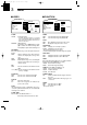
PANEL DESCRIPTION
o EBL2 (VRM2) SWITCH [EBL2 (VRM2)]
/[ ] (pgs. 15–16)
Push to display the electronic bearing line 2 (EBL2)
and the variable range marker 2 (VRM2), and acti-
vate the [Ω≈] for the electronic bearing line selec-
tor and [Ù Ú] for the range marker selector.
• When the VRM1 and EBL1 ($9 %2) are displayed, the
center of VRM2 appears at the intersection point of the
VRM1 and EBL1.
!0 PARALLEL INDEX LINE FUNCTION [PI]/[ ]
Push [EBL1]/[ ] and [EBL2]
/[ ] simultaneously to toggle the paral-
lel index line ON and OFF.
• Push [Ω≈] keys to rotate the lines, and push [Ù Ú]
keys to adjust the line spaces.
!1 MENU SWITCH [MENU]/[ ] (pgs. 6–7)
Push [MENU]/[ ] to toggle the VIDEO, FUNC-
TION, ATA, INT. SETTING and SERVICE MAN
menu. Push [Ù Ú] keys to select the items and
push [Ω≈] keys to change the setting.
!2 HEADING LINE OFF FUNCTION [HL OFF]
/[ ] (p. 9)
Push [BRILL]/[ ] and [MENU]/[ ] simultane-
ously to turn off the heading line temporarily.
!3 GAIN CONTROL [GAIN]/[ ] (p. 9)
Adjusts the receiver amplifier gain.
• Clockwise rotation increases the gain
• Increased gain may increase screen noise.
!4 SEA CLUTTER CONTROL [SEA]/[ ]
(p. 10)
This function serves to eliminate echoes from the
waves at close range.
Reduces the receiver gain for close objects within
a radius of 8 nautical miles (approx.) to eliminate
sea clutter.
Rotate the control fully clockwise to activate the au-
tomatic SEA control function. SEA indicator (@6) ap-
pears in the upper left of the screen.
• Under normal conditions set the SEA to a minimum.
• Use this control with caution when the sea is rough.
!5 RAIN CLUTTER CONTROL [RAIN]/[ ]
(p. 10)
This function eliminates reflection echoes from rain,
snow, fog, etc.
Rotate the control fully counter clockwise to deacti-
vate the RAIN function.
RAIN indicator (@8) disappears.
!6 MAN OVERBOARD [MOB]/[ ]
Push to mark the man overboard point on the
screen. When a crew member falls overboard, push
[MOB]/[ ] for 1 sec. to display the MOB symbol
( ) on the screen.
• MOB readout shows the bearing, distance and esti-
mated time to the MOB point with current speed.
• Push [MOB]/[ ] for 1 sec. to cancel the function.
• Position and bearing data are necessary.
!7 TARGET SWITCH [ATA]/[ ] (pgs. 18–20)
A setup of target caught by ATA (up to 10 targets
can be set).
• Push [Ù Ú Ω ≈] to move the cross cursor on the echo
which you want to plot on the screen before turning the
function ON.
• Select “ATA” function ON in the “ATA” menu, set the ap-
propriate No. DISP, VECT, OWN VECT, ALARM, CPA
LIMIT and TCPA LIMIT setting.
!8 ALARM SWITCH [ALM]/[ ] (p. 17)
Push [ALM]/[ ] to toggle the alarm function ON
and OFF.
Push and hold [ALM] for 1 sec. to enter the alarm
area setting condition.
• Push [Ù Ú Ω ≈] to move the cross cursor to the zone
starting point, then push [ALM] for 1 sec. The starting
ring of the zone is created. Then push [Ù Ú Ω ≈] to fix
the finish point, the desired alarm zone will automatically
form.
!9 EBL1 (VRM1) SWITCH [EBL1 (VRM1)]
/[ ] (pgs. 15–16)
Push to display the electronic bearing line 1 (EBL1)
and the variable range marker 1 (VRM1) and acti-
vate the [Ω≈] for the electronic bearing line selec-
tor, and [ÙÚ] for the range marker selector.
• EBL1 bearing and VRM1 distance are displayed, in the
bottom window.
• When EBL1 and VRM1 are displayed, the beginning of
EBL2 appears at the intersection point of EBL1 and
VRM1.
@0 DISPLAY BRILLIANCE SWITCH [BRILL]/[ ]
(p. 9)
➥Push to increase or decrease the brilliance of the
picture on the display.
➥Push for 1 sec. to select the maximum brilliance.
• The brightness of the symbol, character and illumi-
nation can be adjusted in the “SYMBOL”, “CHAR-
ACTER” and “KEY ILLUM” of the INT. SETTING
menu independently.
MR-1000R2_T2.qxd 04.2.24 10:22 Page 3