I-8090/I-8091 User Manual Version 1.0 06/2001 User Manual Part 1: I-8090 3-axis encoder card Part 2: I-8091 2-axis stepping/servo control card http://www.icpdas.
I-8090/I-8091 User Manual Version 1.0 06/2001 I-8090 Contents 1. Hardware _ 1-4 1.1 I-8000 hardware address 1-4 1.2 Registers of I-8090 Board 1-5 1.3 LED indicator 1-8 1.4 Connection 1-9 2. Software 1-13 2.1 Constants and Functions 1-13 2.2 Eaxmples 1-17 2.2.1 Detect I-8090 card 1-17 2.2.2 Start to use I-8090 card 1-18 2.2.3 Get X, Y, Z-axis encoder counter’s value 1-18 2.2.4 Software 32 bits encoder counter programming 1-20 http://www.icpdas.
I-8090/I-8091 User Manual Version 1.0 I-8091 Contents 1. Introduction 06/2001 _ 2-4 1.1 System Block Diagram 2-4 1.2 DDA technology 2-5 2. Hardware 2-8 2.1 I-8000 hardware address 2-8 2.2 Register of I-8091 board 2-9 2.3 LED indicator 2-10 2.4 Hardware configuration 2-11 2.4.1 Limit switch configuration 2-11 2.4.2 Output pulse mode configuration 2-12 2.4.3 Direction configuration 2-12 2.4.4 Turn Servo ON/OFF (Hold ON/OFF) 2-12 2.4.5 Automatic protection 2-12 2.4.
I-8090 User Manual Version 1.0 06/2001 I-8090 3-axis encoder card User Manual Version 1.0 06/2001 Edition Warranty: All products manufactured by ICP DAS are warranted against defective materials for one year from the date of delivery to the original purchaser Warning: ICP DAS assumes no liability for damage consequent to the use of this product. ICP DAS reserves the right to change this manual at any time without notice. The information furnished by ICP DAS is believed to be accurate and reliable.
I-8090 User Manual Version 1.0 I-8090 06/2001 3-axis encoder card I-8090 is a 3-axis encoder counter board on I-8000 platform. I-8090 encoder card has internal digital filter, 16 bits counter and high counting rate 1Mpps. The application of I-8090 board is position/distance measurement, velocity measurement, feedback for motor control, handwheel input and so on.
I-8090 User Manual Version 1.0 06/2001 8090 Contents _ 1. Hardware 1-4 1.1 I-8000 hardware address 1-4 1.2 Registers of I-8090 Board 1-5 1.3 LED indicator 1-8 1.4 Connection 1-9 2. Software 1-13 2.1 Constants and Functions 1-13 2.2 Eaxmples 1-17 2.2.1 Detect I-8090 card 1-17 2.2.2 Start to use I-8090 card 1-18 2.2.3 Get X, Y, Z-axis encoder counter’s value 1-18 2.2.4 Software 32 bits encoder counter programming 1-20 http://www.icpdas.
I-8090 User Manual Version 1.0 06/2001 1. Hardware _ 1.1 I-8000 hardware address The hardware address of I-8000 main system is fixed as following table. There are 4 slots I-8000 and 8 slots I-8000.
I-8090 User Manual Version 1.0 06/2001 1.2 Registers of I-8090 board The I-8090 card’s registers table as following. Register Add. R/W Bit 7 Bit 6 Bit 5 Bit 4 Bit 3 Bit 2 Bit 1 Bit 0 ID 0x00 R 0x0D XDATA 0x01 R X-axis encoder value YDATA 0x02 R Y-axis encoder value ZDATA 0x03 R Z-axis encoder value INDEX R 0x04 ZI YI XI XCTRL 0x00 W S1 S0 /RST /INH /SEL YCTRL 0x01 W S1 S0 /RST /INH /SEL ZCTRL 0x02 W S1 S0 /RST /INH /SEL Register Add.
I-8090 User Manual Version 1.0 06/2001 /SEL=0 (ZCTRL register), the high byte can be read out when set /SEL=1 (ZCTRL register). Register Add. R/W Bit 7 Bit 6 Bit 5 Bit 4 Bit 3 Bit 2 Bit 1 Bit 0 INDEX 0x04 R ZI YI XI The index input C+/C- can read out from this register. These bits are active high. XI : indicate the index of X-axis (C+/C- input). YI : indicate the index of Y-axis (C+/C- input). ZI : indicate the index of Z-axis (C+/C- input). Register Add.
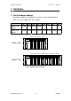
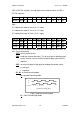
I-8090 User Manual Version 1.0 06/2001 CW CCW counter 1 2 3 2 1 CW/CCW Counting Mode X2=0 Fig(3) CW/CCW counting mode 10 : Pulse/Direction counting mode Pulse Direction counter X2=0 1 2 3 2 1 Pulse/Direction Counting Mode Fig(4) Pulse/Direction counting mode Example: assign counting mode x_mode=y_mode=z_mode=0x00; card[cardNo].ctrl1 = 0x07 | x_mode; card[cardNo].ctrl2 = 0x07 | y_mode; card[cardNo].ctrl3 = 0x07 | z_mode; outportb(card[cardNo].base + WR1, card[cardNo].
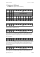
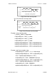
I-8090 User Manual Version 1.0 06/2001 1.3 LED Indicator power 1A 1B 1C 2A 2B 2C 3A 3B Fig(5) I-8090 LED indicator Where 1A, 1B, 1C indicate X-axis’s 1A+/1A-, 1B+/1B-, 1C+/1C- signal input. 2A, 2B, 2C indicate Y-axis’s 2A+/2A-, 2B+/2B-, 2C+/2C- signal input. 3A, 3B, indicate Z-axis’s 3A+/3A-, 3B+/3B- signal input. http://www.icpdas.
I-8090 User Manual Version 1.0 06/2001 1.
I-8090 User Manual Version 1.0 06/2001 E5V 8 Isolated 5V supply, max. 50mA (sum of pin 4,8,12) EGND 21 Signal ground 3A+ 9 A+ input of Z-axis encoder 3A- 22 A- input of Z-axis encoder 3B+ 10 B+ input of Z-axis encoder 3B- 23 B- input of Z-axis encoder 3C+ 11 C+ input of Z-axis encoder 3C- 24 C- input of Z-axis encoder E5V 12 Isolated 5V supply, max.
I-8090 User Manual Version 1.
I-8090 User Manual Version 1.
I-8090 User Manual Version 1.0 06/2001 2. Software _ User’s applications could be compiled under DOS Turbo/Borland C/C++ environment. It should be include i8090.h and i8090.LIB to compile the target execution file. The execution files can be downloaded under I-8000 main system (execute 7188x.exe), and then run the target execution file as under PC system. About the I-8000’s resource or environment, please refer to the manual of I-8000 system or its software programming guide.
I-8090 User Manual Version 1.0 06/2001 address: hardware address which defined at chapter 1.1 Return: “YES” : registration successful “NO” : registration failure. Example: This example will assign I-8090 card address=0x080 as CARD1 (1). Then initial the I-8090 card and reset X,Y,Z axis encoder counter value to 0.
I-8090 User Manual Version 1.0 06/2001 i8090_INIT_CARD(CARD1, ENC_QUADRANT, ENC_QUADRANT, ENC_QUADRANT); (3) unsigned int i8090_GET_ENCODER(unsigned char cardNo, unsigned char axis) This command will return the counter value of the selected “axis” and “cardNo”. cardNo: 0~19, select which card. axis : select which axis. 1 : X-axis 2 : Y-axis 3 : Z-axis return : a 16 bits unsigned integer value.
I-8090 User Manual Version 1.0 06/2001 32 bits encoder counts command sets (6) void i8090_ENCODER32_ISR(unsigned char cardNo) (7) void i8090_RESET_ENCODER32(unsigned char cardNo, unsigned char axis) (8) long i8090_GET_ENCODER32(unsigned char cardNo, unsigned char axis) cardNo: 0~19, select which card. axis : select which axis. 1 : X-axis 2 : Y-axis 3 : Z-axis The above three commands provided a software method to get 32 bits encoder counts.
I-8090 User Manual Version 1.0 06/2001 2.2 examples 2.2.1 Detect I-8090 card //--------------------------------------------------// detect i8090,i8091,i8092 card //--------------------------------------------------#include "8000.h" #include "i8090.
I-8090 User Manual Version 1.0 06/2001 return i8092; default: Print("Slot %d = No Card\r\n",SlotNum); return NOCARD; }; Delay(500); }; } 2.2.2 Start to use I-8090 card #define CARD1 1 if (i8090_REGISTRATION(CARD1, PortAddress[0])==YES) { i8090_INIT_CARD(CARD1, ENC_QUADRANT, ENC_QUADRANT, ENC_QUADRANT); i8090_RESET_ENCODER(CARD1, X_axis); i8090_RESET_ENCODER(CARD1, Y_axis); i8090_RESET_ENCODER(CARD1, Z_axis); } else { Print(“ Not found I-8090 card in slot 0!”); return; } 2.2.
I-8090 User Manual Version 1.0 06/2001 card[cardNo].ctrl1 &= 0xFC; //1111 1100 low byte outportb(card[cardNo].base + WR1, card[cardNo].ctrl1); value = inportb(card[cardNo].base + RD1); card[cardNo].ctrl1 |= 0x01; //0000 0001 high byte outportb(card[cardNo].base + WR1, card[cardNo].ctrl1); value += inportb(card[cardNo].base + RD1)*256; card[cardNo].ctrl1 |= 0x03; //0000 0011 outportb(card[cardNo].base + WR1, card[cardNo].ctrl1); break; case Y_axis: card[cardNo].
I-8090 User Manual Version 1.0 06/2001 break; default : break; } return value; } 2.2.4 Software 32 bits encoder counter programming //-------------------------------------------------------------------// demo1.
I-8090 User Manual Version 1.
I-8090 User Manual Version 1.
I-8090 User Manual Version 1.
I-8090 User Manual int Version 1.
I-8090 User Manual Version 1.
I-8090 User Manual Version 1.0 06/2001 switch (ShowAxis) { case 0: ShowLedValue(x_value,X_axis); break; case 1: ShowLedValue(y_value,Y_axis); break; case 2: ShowLedValue(z_value,Z_axis); break; }; if (x_index) LedRunOff(); else LedRunOn(); if (y_index) LedCommOff(); else LedCommOn(); if (z_index) LedBattOff(); else LedBattOn(); } while (!Kbhit()); } http://www.icpdas.
I-8091 User Manual Version 1.0 06/2001 I-8091 2-axis stepping/servo motor control card User Manual Version 1.0 06/2001 Edition Warranty: All products manufactured by ICP DAS are warranted against defective materials for one year from the date of delivery to the original purchaser Warning: ICP DAS assumes no liability for damage consequent to the use of this product. ICP DAS reserves the right to change this manual at any time without notice.
I-8091 User Manual Version 1.0 06/2001 I-8091 2-axis Stepping/Servo Motor Control Card The I-8091 card is a 2-axis command-type stepping motor control card on I-8000 platform, it also can be used as servo motor control (pulse input type). This card has an embedded CPU which performs motion commands transfered from I-8000 main system to increase the system performance. A 2Kbytes-FIFO is introduced as command buffer. This buffer can provide over 700ms buffer time.
I-8091 User Manual Version 1.0 I-8091 Contents 06/2001 _ 1. Introduction 2-4 1.1 System Block Diagram 2-4 1.2 DDA technology 2-5 2. Hardware 2-8 2.1 I-8000 hardware address 2-8 2.2 Register of I-8091 board 2-9 2.3 LED indicator 2-10 2.4 Hardware configuration 2-11 2.4.1 Limit switch configuration 2-11 2.4.2 Output pulse mode configuration 2-12 2.4.3 Direction configuration 2-12 2.4.4 Turn Servo ON/OFF (Hold ON/OFF) 2-12 2.4.5 Automatic protection 2-12 2.4.
I-8091 User Manual Version 1.0 06/2001 1. Introduction _ 1.1 System Block Diagram The I-8091 stepping motor control card is a micro-computer controlled, 2-axis pulse generation card. It includes a 2Kbytes-FIFO to receive motion command from host, a micro-computer for profile generation and protection, 2-axis DDA chip to execute DDA function when interpolation command is used, 2500Vrms optical isolation inserted for industrial application.
I-8091 User Manual Version 1.0 06/2001 1.2 DDA Technology The DDA chip is the heart of I-8091 card, it will generate equal-space pulse train corresponding to specific pulse number during a DDA period. This mechanism is very useful to execute pulse generation and interpolation function. The DDA period can be determined by DDA cycle. Table(1) shows the relation among DDA cycle, DDA period and output pulse rate. When DDA cycle set to 1, the DDA period is equal to (1+1)x1.024ms = 2.048ms.
I-8091 User Manual Version 1.0 06/2001 (1) The required max. output pulse rate. PRmax = Vmax*N/60 2047 PRmax = ( DDAcycle + 1) * 1. 024ms PRmax : max. output pulse rate. Vmax : max. speed (rpm). N : the pulse number of stepping motor per revolution. (pulse/rev). 2. The required speed resolution. The maximum output pulse number is Np(0~2047), therefore the speed resolution is Vmax(max. speed)/Np. The DDA cycle can be obtained by following equation. Np PRmax = ( DDAcycle + 1) * 1. 024ms 3.
I-8091 User Manual Version 1.0 06/2001 High Speed = 247 pulse (4166.67*58*0.001024) The above results means that maximum speed is 500rpm when send command i8091_SET_VAR(0, 58, 2, 2, 247) to I-8091 card. Example: Pulse type input Servo Motor The specification of servo motor is 8000 pulse/rev, max. speed 3000 rpm, speed resolution 2 rpm. The required max.
I-8091 User Manual Version 1.0 06/2001 2 Hardware _ 2.1 I-8000 hardware address The hardware address of I-8000 main system is fixed as following table. There are 4 slots I-8000 and 8 slots I-8000.
I-8091 User Manual Version 1.0 06/2001 2.2 Registers of I-8091 board The I-8091 card’s registers table as following. Register Add. R/W ID 0x00 R LIMIT1 0x01 R LIMIT2 0x02 R WRFF 0x01 W Bit 7 Bit 6 Bit 5 /EMG /FFFF /FFEF /LS14 /YSTOP /XSTOP /LS24 /LS11 /ORG1 /LS21 /ORG2 Command port Reset FIFO Register Add.
I-8091 User Manual Version 1.0 06/2001 '/XSTOP' or '/YSTOP' signal become to '0'. Register Add. R/W WRFF Bit 7 Bit 6 0x01 W Bit 5 Bit 4 Bit 3 Bit 2 Bit 1 Bit 0 Command port I-8091 driver will send motion command by way of this register. Please do not use this register to write any thing, or I-8091 will not operate properly. Register Add.
I-8091 User Manual Version 1.0 06/2001 2.4 Hardware Configuration 2.4.1 Limit switch configuration Because the profile generation and protection is executed by the CPU on I-8091 card, the limit switches must configure as following diagram. The motion command just can work properly. CCW/BW CW/FW Motor ccm LS11 ORG1 LS14 /LS11 /ORG1 /LS14 EXT_GND X axis /EMG Emer gency Fig.(5) Limit switch configuration of X axis CCW/BW CW/FW Motor ccm LS21 ORG2 LS24 /LS21 /ORG2 /LS24 EXT_GND Y axis Fig.
I-8091 User Manual Version 1.0 06/2001 2.4.2 Output pulse mode configuration I-8091 card provide two kind output method. (a) CW/CCW mode (b) Pulse/Direction mode The command i8091_SET_MODE(cardNo, modeX, modeY) provide parameters CW_CCW (0) and PULSE_DIR (1) to define output pulse mode. CW Mode = 0 (CW_CCW) CCW Pulse Mode = 1 (PULSE_DIR) Direction Fig.(7) Output pulse mode 2.4.
I-8091 User Manual Version 1.0 06/2001 X-axis will immediately stop when LS14 is touched. To release this protection as long as X-axis move toward CCW/BW direction. (b) If X-aixs command is executing and moving toward CCW/BW direction, X-axis will immediately stop when LS11 is touched. To release this protection as long as X-axis move toward CW/FW direction. (c) If Y-aixs command is executing and moving toward CW/FW direction, Y-axis will immediately stop when LS24 is touched.
I-8091 User Manual Version 1.0 06/2001 2.5 Connection 2.5.1 Pin assignment of connector CN2 CN2 DB25M-90 +5V CW_PULSE1 CW_PULSE2 CCW_DIR1 CCW_DIR2 HOLD1 HOLD2 GND EXT_VCC (12~24V) ORG1 ORG2 LS11 LS21 LS14 LS24 EMG EXT_GND 1 14 2 15 3 16 4 17 5 18 6 19 7 20 8 21 9 22 10 23 11 24 12 25 13 Fig.(8) CN2 connector Table of CN2 connector’s pin assignment pin name pin number +5V 1 Internal +5V power, Max.
I-8091 User Manual Version 1.0 EXT_VCC 19 External power(12~24V) for limit switches /ORG2 20 Y-axis original (home) limit switch /LS21 21 Y-axis limit switch 22,23 06/2001 No used /LS24 24 Y-axis limit switch EXT_GND 25 External ground for limit switch 2.5.2 The internal circuit of CW_PULSE, CCW_DIR, HOLD When output these signal as 1, it can source 15mA(max.). When output these signal as 0, it can sink 50mA(max.) +5V 330 CW_PULSE1 CCW_DIR1 HOLD1 CW_PULSE2 CCW_DIR2 HOLD2 i8091 Fig.
I-8091 User Manual Version 1.0 06/2001 2.5.4 Example of connection +5V 1 3 6 5 4 CW_PULSE1 CW + 1 4 CW - 2 3 +5V 1 3 6 5 4 CCW_DIR1 CCW + 1 4 CCW - 2 3 HOLD + 1 4 HOLD - 2 3 +5V 1 3 6 5 4 HOLD1 GND DGND FAN-OUT TYPE (VEXTA) DRIVER Fig.(11) fan-out type driver (VEXTA's motor driver) +5V COM 1 3 6 5 4 CW_PULSE1 CW/PULSE 1 4 2 3 1 4 2 3 1 4 2 3 +5V 1 3 6 5 4 CCW_DIR1 CCW/DIR +5V 1 3 6 5 4 HOLD1 HOLD GND DGND SINK TYPE DRIVER Fig.
I-8091 User Manual Version 1.0 06/2001 CN2 DB25M-90 S5V CW_PULSE1 CW_PULSE2 CCW_DIR1 CCW_DIR2 HOLD1 HOLD2 SGND EXT_VCC EXT_VCC (12V~24V) PHOME1 PHOME2 PLS11 PLS21 PLS14 PLS24 PEMG EXT_GND 1 14 2 15 3 16 4 17 5 18 6 19 7 20 8 21 9 22 10 23 11 24 12 25 13 CN2 DB25M-90 1A+ 1A1B+ 1B1C+ 1CE5V EGND 2A+ 2A2B+ 2B2C+ 2CE5V EGND 3A+ 3A3B+ 3B3C+ 3CE5V EGND EGND S8091 card 1 14 2 15 3 16 4 17 5 18 6 19 7 20 8 21 9 22 10 23 11 24 12 25 13 S8090 card Fig.
I-8091 User Manual Version 1.0 06/2001 3. Software _ User’s applications could be compiled under DOS Turbo/borland C/C++ environment. It should be include i8091.h and i8091.LIB to compile the target execution file. The execution files can be downloaded under I-8000 main system (execute 7188x.exe), and then run the target execution file as under PC system. About the I-8000’s resource or environment, please refer to the manual of I-8000 system or its software programming guide.
I-8091 User Manual Version 1.0 06/2001 (b)If X-aixs command is executing and moving toward CCW/BW direction, X-axis will immediately stop when LS11 is touched. To release this protection as long as X-axis move toward CW/FW direction. (c) If Y-aixs command is executing and moving toward CW/FW direction, Y-axis will immediately stop when LS24 is touched. To release this protection as long as Y-axis move toward CCW/BW direction.
I-8091 User Manual Version 1.0 06/2001 3.1.1 Setting commands (1) unsigned char i8091_REGISTRATION(unsigned char cardNo, unsigned int address); In order to distinguish more than one I-8091 card in I-8000 platform, the I-8091 cards should be registrated before using it. This command will assign a card number=“cardNo” to I-8091 card address=”address” . If there is not I-8091 at the given address, this command will return “NO”. cardNo : board number 0~19.
I-8091 User Manual Version 1.0 06/2001 Restriction: 1 ≤ DDA _ cycle ≤ 254 1 ≤ Acc _ Dec ≤ 200 1 ≤ Low _ Speed ≤ 200 Low _ Speed ≤ High _ Speed ≤ 2047 Low_Speed >= Acc_Dec default value DDA_cycle = 10 Acc_Dec = 1 Low_Speed = 10 High_Speed = 100 Example: i8091_SET_VAR(1, 5, 2, 10, 150); where DDA_cycle = 5 --> DDA period = (5+1)*1.024ms = 6.144ms Acc_Dec = 2 --> Acc/Dec speed = 2/(6.144ms)^2 = 52981 p/s^2 Low_Speed = 10 --> low speed = 10/6.144ms = 1628pps High_Speed = 150 --> high speed = 150/6.
I-8091 User Manual Version 1.0 06/2001 1 : REVERSE_DIR (5) i8091_SET_MODE(unsigned char cardNo, unsigned char modeX, unsigned char modeY) I-8091 card provide two kind output method. cardNo : board number 0~19.
I-8091 User Manual Version 1.0 06/2001 set as N.C., those limit switches are active high. The auto-protection will automatically change the judgement whatever it is N.O. or N.C.. Limit switches: ORG1, LS11, LS14, ORG2, LS21, LS24, EMG. cardNo : card number 0~19. sw: 0(NO) normal open (default). 1(YES) normal close. http://www.icpdas.
I-8091 User Manual Version 1.0 06/2001 3.1.2 Stop Commands (8) i8091_STOP_X(unsigned char cardNo) to stop X axis. cardNo : board number 0~19. (9) i8091_STOP_Y(unsigned char cardNo) to stop Y axis. cardNo : board number 0~19. (10) i8091_STOP_ALL(unsigned char cardNo) to stop X, Y axis immediatly. cardNo : board number 0~19. This command will clear all of commands pending in the FIFO. The i8091_RESET_SYSTEM can be used as software emergency stop.
I-8091 User Manual Version 1.0 06/2001 3.1.3 Simple motion commands (12) i8091_LSP_ORG(unsigned char cardNo, unsigned char DIR, unsigned char AXIS) Low speed move , and stop when ORG1/ORG2 limit switch is touched. cardNo : board number 0~19. ORG Low speed Example: i8091_LSP_ORG(1, CCW, X_axis); i8091_LSP_ORG(1, CCW, Y_axis); (13) i8091_HSP_ORG(unsigned char cardNo, unsigned char DIR, unsigned char AXIS) High speed move , and stop when ORG1/ORG2 limit switch is touched. cardNo : board number 0~19.
I-8091 User Manual Version 1.0 06/2001 i8091_LSP_PULSE_MOVE(1, X_axis, -2000); i8091_LSP_PULSE_MOVE(1, Y_axis, 20000); i8091_LSP_PULSE_MOVE(1, Y_axis, -2000); where when pulseN>0, move toward CW/FW direction when pulseN<0, move toward CCW/BW direction (15) i8091_HSP_PULSE_MOVE(unsigned char cardNo, unsigned char AXIS, long pulseN) High speed move #pulseN. cardNo : board number 0~19.
I-8091 User Manual Version 1.0 06/2001 Low speed Example: i8091_LSP_MOVE(1, CW, X_axis); getch( ); i8091_STOP_X(1); i8091_LSP_MOVE(1, CCW, Y_axis); getch( ); i8091_STOP_Y(1); (17) i8091_HSP_MOVE(unsigned char cardNo, unsigned char DIR, unsigned char AXIS) High speed move toward direction DIR. It can be stop by i8091_STOP_X or i8091_STOP_Y or i8091_STOP_ALL command. cardNo : board number 0~19.
I-8091 User Manual Version 1.0 06/2001 command i8091_STOP_X(), i8091_STOP_Y(), i8091_STOP_ALL(), or i8091_SLOW_STOP(). cardNo : board number 0~19. axis : selected axis. 1 : X axis 2 : Y axis dir : moving direction.
I-8091 User Manual Version 1.0 06/2001 getch( ); i8091_SLOW_DOWN(1, X_axis); getch( ); i8091_STOP_X(1); (20) i8091_SLOW_STOP(unsigned char cardNo, unsigned char AXIS) to decelerate to stop. cardNo : board number 0~19. SLOW_STOP Example: i8091_HSP_MOVE(1, CW, Y_axis); getch( ); i8091_SLOW_STOP(1, Y_axis); http://www.icpdas.
I-8091 User Manual Version 1.0 06/2001 3.1.4 Interpolation commands (21) i8091_INTP_PULSE(unsigned char cardNo, int Xpulse, int Ypulse) This command will move a short distance (interpolation short line) in X-Y plane. This command provided a method for user to generate an arbitrary curve in X-Y plane. Y Y 10 (Xpulse,Ypulse) 9 3 4 2 X 8 5 6 7 1 X cardNo : board number 0~19.
I-8091 User Manual Version 1.0 06/2001 Restriction: −524287 ≤ # Xpulse ≤ 524287 −524287 ≤ #Ypulse ≤ 524287 Example: i8091_INTP_LINE(1,2000,-3000); i8091_INTP_LINE(1,-500,200); (23) i8091_INTP_LINE02(unsigned char cardNo, long x, long y , unsigned int speed , unsigned char acc_mode) This command will move a long interpolation line in X-Y plane. Host will automaticly generate a trapezoidal speed profile of X-axis and Y-axis by state-machine-type calculation method.
I-8091 User Manual Version 1.0 06/2001 automaticly generate a trapezoidal speed profile of X-axis and Y-axis by state-machine-type calculation method. The i8091_INTP_CIRCLE02() only set parameters into the driver. User can directly call the do { } while (i8091_INTP_STOP( ) !=READY) to execute the computing entity. cardNo : board number 0~19. x, y : center point of circle relate to present position. dir : moving direction.
I-8091 User Manual Version 1.0 06/2001 x, y : end point of arc relate to present position. R : radius of arc. if R>0 , the arc < 180degree if R<0 , the arc > 180 degree dir : moving direction.
I-8091 User Manual Version 1.0 06/2001 Example: i8091_INTP_ ARC02(1,2000,-2000,2000,CW,100,0); do { } while( i8091_INTP_STOP()!=READY) ; //call state machine (26) unsigned char i8091_INTP_STOP() The above 3 state-machine-type interpolation commands i8091_INTP_LINE02(), i8091_INTP_CIRCLE02() and i8091_INTP_ARC02() must use i8091_INTP_STOP() simultaneously. The state-machine-type interpolation commands are only set parameters into the driver. The computing entity is in i8091_INTP_STOP().
I-8091 User Manual Version 1.0 06/2001 3.1.5 Others (27) unsigned char i8091_LIMIT_X(unsigned char cardNo) to request the condition of X-axis limit switches cardNo : board number 0~19. MSB 7 6 5 4 3 2 1 0 LSB /EMG /FFFF /FFEF /LS14 xx xx /LS11 /ORG1 /ORG1 : original point switch of X-axis, low active. /LS11, /LS14 : limit switches of X-axis, low active, which must be configured as Fig.(5). /EMG : emergency switch, low active.
I-8091 User Manual Version 1.0 06/2001 (30) i8091_WAIT_Y(unsigned char cardNo) to wait Y-axis going to STOP state. cardNo : board number 0~19. (31) unsigned char i8091_IS_X_STOP(unsigned char cardNo) To check whether X axis is STOP or not. 0 (NO) : not yet stop Return value 1 (YES) : stop (32) unsigned char i8091_IS_Y_STOP(unsigned char cardNo) To check whether Y axis is STOP or not. 0 (NO) : not yet stop Return value 1 (YES) : stop http://www.icpdas.
I-8091 User Manual Version 1.0 06/2001 3.2 Start up and end of program Start up program When you are going to use I-8091 card, there are some commands must be implement in previous. i8091_REGISTRATION(CARD1,0x80) set CARD1 address, (where CARD1=1) i8091_RESET_SYSTEM(CARD1); reset system i8091_SET_VAR(CARD1, DDA, AD, LSP, HSP); set DDA cycle, accelerating/decelerating speed, low speed and high speed value i8091_SET_DEFDIR(CARD1, xdir, ydir); define direction.
I-8091 User Manual Version 1.0 06/2001 } i8091CardType; i8091CardType card1; //------------------------------------------------------------------------void main () { card1.address=PortAddress[i8091Slot]; card1.DDA = 10; card1.AD = 5; card1.LSP = 5; card1.HSP = 100; card1.xmode = CW_CCW; card1.ymode = CW_CCW; card1.xdir = NORMAL_DIR; card1.ydir = NORMAL_DIR; card1.xson = ON; card1.yson = ON; card1.NCmode= OFF; i8091_REGISTRATION(CARD1, card1.
I-8091 User Manual Version 1.0 06/2001 4. Example 4.1 Detect I-8091 card //--------------------------------------------------// detect i8090,i8091,i8092 card //--------------------------------------------------#include "8000.h" #include "s8090.
I-8091 User Manual Version 1.0 06/2001 return i8092; default: Print("Slot %d = No Card\r\n",SlotNum); return NOCARD; }; Delay(500); }; } 4.2 Example: DEMO.cpp //--------------------------------------------------------------------------// demo.