PCI-P8R8/P16R16/P16C16/P16POR16 User’s Manual Warranty All products manufactured by ICP DAS are warranted against defective materials for a period of one year from the date of delivery to the original purchaser. Warning ICP DAS assumes no liability for damages consequent to the use of this product. ICP DAS reserves the right to change this manual at any time without notice. The information furnished by ICP DAS is believed to be accurate and reliable.
Table of Contents 1. INTRODUCTION ....................................................................................................................3 1.1 FEATURES AND APPLICATIONS ............................................................................................4 1.2 BLOCK DIAGRAM ................................................................................................................5 1.3 SPECIFICATIONS ...............................................................................
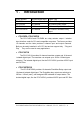
1. Introduction Model Number Isolated Digital Input Output Type PCI-P8R8 8 Channel 8 Channel Relay Output PCI-P16R16 16 Channel 16 Channel Relay Output PCI-P16C16 16 Channel 16 Channel Open-Collector Output PCI-P16POR16 16 Channel 16 Channel PhotoMos-Relay Output • PCI-P8R8 / PCI-P16R16 The PCI-P16R16 and PCI-P8R8 are relay actuator output / isolation input interface cards for PCs and compatible computers.
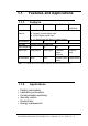
1.1. 1.1.1. Features and Applications Features PCI-P8R8 Common Features PCI-P16R16 PCI-P16C16 PCIP16POR16 5V PCI Bus add-on card Optically isolated digital input AC/DC digital signed input AC digital input with filter by jumper setting Input channel 8 16 Input type Optically isolated digital input 16 16 Output channel 8 16 16 16 Output type Relay output Transistor (Opencollector) PhotoMos Relay None External Power Output Status status Relay Output Led indicators None Table 1-1.
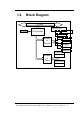
1.2. Block Diagram PCI BUS P8R8 / P16R16 EEPROM PCI Controller Relay P16C16 Relay Transistor Buffers & Drivers Transistor PhotoMos Relay PhotoMos Relay Transistor P16POR1 Transistor PhotoMos PhotoMos Photo-couple Buffers & Filters Photo-couple Photo-couple Photo-couple Figure 1-1: Functional Block diagram. PCI-P8R8/P16R16/P16C16/P16POR16 User’s Manual (Ver.2.
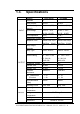
1.3. Specifications Product INPUT PCI-P16R16 Channels 16 8 Photo-coupler PC-814 PC-814 Input-Current (per channel) 20 mA max (24V) 20 mA max (24V) Input-Voltage AC/DC 5 - 24 V (AC 50 - 1K HZ) 1.2 KΩ AC/DC 5 - 24 V (AC 50 - 1K HZ) 1.2 KΩ Input Impedance Withstanding Voltage 1KV 1KV Response Time Without Filter 20µS Without Filter 20µS With Filter 2.2mS With Filter 2.2mS Relay Output Channels 16 8 Relay Type 8 SPDT 8 SPST 4 SPDT 4 SPST Contact Rating AC: 120V / 0.
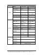
Product INPUT PCI-P16C16 Channels 16 16 Photo-coupler PC-814 PC-814 Input-Current (per channel) 20 mA max (24V) 20 mA max (24V) Input-Voltage AC/DC 5 - 24 V (AC 50 - 1K HZ) 1.2 KΩ AC/DC 5 - 24 V (AC 50 - 1K HZ) 1.2 KΩ Input Impedance Withstanding Voltage 1KV 1KV Response Time Without Filter 20µS Without Filter 20µS With Filter 2.2mS With Filter 2.
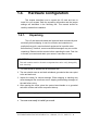
1.4. Hardware Configuration This chapter describes how to unpack this I/O card and how to install it to your system. Both the unpacking information and the jumper settings are described in the following text. This manual should be carefully read before installation. 1.4.1. Unpacking This I/O card was well-tested and inspected both mechanically and electrically before shipping. It was free of marks and scratches our quality delivery policy requires that all equipment be in perfect order before delivery.
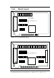
1.4.2. Board Layout PCI-P8R8 Input Resistor: 1.2KΩ JP8..........JP1 Figure 1-2. PCI–P8R8 Board Layout. PCI-P16R16 Input Resistor: 1.2KΩ JP8......….JP1 JP16 —— JP9 Figure 1-3. PCI–P16R16 Board Layout. PCI-P8R8/P16R16/P16C16/P16POR16 User’s Manual (Ver.2.
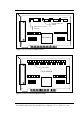
Transistor External Power LED indicator External Power protection (Pico Fuse) PCI-P16C16 JP16 — JP9 JP8............JP1 Figure 1-4. PCI-P16C16 Board Layout LED indicator PCI-P16POR16 JP8...........JP1 JP16 —— JP9 Figure 1-5. PCI-P16POR16 Board Layout PCI-P8R8/P16R16/P16C16/P16POR16 User’s Manual (Ver.2.
1.4.3. Jumper Setting • For PCI-P8R8 / P16R16 / P16C16 / P16POR16 You can change the I/O card configuration simply by setting the jumpers on this board. Each digital input channel can be jumperconfigured as a single-pole, RC filter with a time constant of 1.2 ms. The table listed below shows each digital input channel and the corresponding jumper.
1.5. Pin Assignments CON 1 PCI-P8R8 / PCI-P16R16 Pin Assignment PCI CON 2 CON 2 Extender Cable NO: Normal Open COM: Common NC: Normal Close DIA: Digital Input (Point A) DIB: Digital Input (Point B) PCI-P8R8/P16R16/P16C16/P16POR16 User’s Manual (Ver.2.
CON 1 PCI-P16C16 Pin Assignment CON 2 CON 2 External Cable Ext. Power: External Power Input GND: External Power Ground OUT: Open Collector Output DIA: Digital Input (Point A) DIB: Digital Input (Point B) PCI-P8R8/P16R16/P16C16/P16POR16 User’s Manual (Ver.2.
CON 1 PCI-P16POR16 Pin Assignment CON 2 CON 2 8 9 10 11 12 13 14 15 DIA: Digital Input (Point A) DIB: Digital Input (Point B) B B B B B B B B 8 9 10 11 12 13 14 15 External Cable NO CM PCI-P8R8/P16R16/P16C16/P16POR16 User’s Manual (Ver.2.
2. Hardware applications Model Number OUTPUT Input PCI-P8R8 / PCI-P16R16 Relay Output Optical isolation PCI-P16C16 Transistor Output (Open collector) Optical isolation PCI-P16POR16 PhotoMos Relay Output Optical isolation 2.1 Relay Output • For PCI-P8R8 / PCI-P16R16 Only Whenever data is written data to the output control register, the relays will switch to NC or NO as specified by the control code. A`1'in the control register will energize the corresponding relay.
Heavy Loading Application ( > 0.3 A ) : P16R16DI O Relay Power Relay Contact Power Relay Heavy Loading Figure 2-3. Heavy load relay circuit. 2.2 Open Collector Output • For PCI-P16C16 Only The PCI-P16C16 provides 16-channel open collector outputs and 4 channels per common power. Each common power has designed fuse protection and LED indicated status. Wiring diagrams - Load - Load - Load - Load PCI-P16C16 Load current per channel: 30Vdc/600mA (max.
2.3 PhotoMos Relay Output • For PCI-P16POR16 Only The PCI-P16POR16 includes 16 normally open, form A, PhotoMOS relays. The board can eliminate ground-loop problems and isolate the computer from damaging voltages. Use the PCI-P16POR16 to switch loads, up to 350VAC and 130mA. 350VAC@130mA(max.) NO Load Power AC/DC CM NO CM Measurement Meter AC/DC Signal PCI-P16POR16 PCI-P8R8/P16R16/P16C16/P16POR16 User’s Manual (Ver.2.
2.4 Isolated Input • For PCI-P8R8 / P16R16 / P16C16 / P16POR16 Reading the isolation input register will give the digital input state of the photocouple (isolation input). Figures 2-3 and 2-4 show the basic circuit of the digital input. Switch DIA 0 Internal Circuit If Using AC Signal, JP1 must be shorted 2-3!! 5 ~ 24 V AC/DC DIB 0 Figure 2-3. Basic Digital Input Circuit. PCI-P8R8/P16R16/P16C16/P16POR16 User’s Manual (Ver.2.
Although the normal input voltage range is 5 to 24V AC or DC, the input can still be changed to a larger range by choosing suitable external resistors. The following figure shows how to connect to a larger input. Please note that the input current should be limited between 2mA to 20mA; too large an input current will burn down the internal resistor Ri, while too low of an input current will not active the photo-coupler isolator. Calculate input voltage and current, then replace resister Ri. Ri = 1.
3. Software Installation Guide • FOR PCI-P8R8/PCI-P16R16/PCI-P16C16/PCI-P16POR16 The software package for this card consists of CD-ROM. Please choose the exact disk for setup according to your PC platform. 3.1 Plug and Play of Windows 95/98/2000/XP Because Windows 95/98/2000/XP provides the Plug and Play, two stages must be completed to setup the I/O card. After plugging the PCI-P8R8/P16R16/P16C16/P16POR16 on the main-board and turning on the power, you will see these the following windows.
Figure 2. Click on the “Next >” button to search device Figure 3. Click on the “Next>” button to search drivers PCI-P8R8/P16R16/P16C16/P16POR16 User’s Manual (Ver.2.
Figure 4. Select the second item and click “Next >” Figure 5. Select the item “Other devices” and click “Next>” PCI-P8R8/P16R16/P16C16/P16POR16 User’s Manual (Ver.2.
Figure 6. Click the “Have Disk button…” Figure 7. Click “Browse” to select driver PCI-P8R8/P16R16/P16C16/P16POR16 User’s Manual (Ver.2.
Figure 8. Click “OK” after selecting the “P16R16.inf”driver. This folder corresponds to on the CD-ROM drive. (Note: PCI-P8R8 uses the driver P8R8.inf) Figure 9. Click “OK” (Note: PCI-P8R8 uses the driver P8R8.inf) PCI-P8R8/P16R16/P16C16/P16POR16 User’s Manual (Ver.2.
Figure 10. Click “Next>” Figure 11. Click “Next>” (Note: PCI-P8R8 uses the driver P8R8.inf) PCI-P8R8/P16R16/P16C16/P16POR16 User’s Manual (Ver.2.
Figure 12. Click “Finish” Figure 13. Double click the item “System” in the “Control Panel” folder PCI-P8R8/P16R16/P16C16/P16POR16 User’s Manual (Ver.2.
Figure 14. Select the device “PCI-P16R16”(or PCI-P8R8) and click “Properties” Figure 15. Please ensure that this device has no conflicts with other devices. PCI-P8R8/P16R16/P16C16/P16POR16 User’s Manual (Ver.2.
3.2 Software Installation for DOS Here’s the DOS software installation: Refer to the install.bat in sub-directory of P16R16 with CD-ROM. After installation, the sub-directory is as follows: /**** Demo code, Lib for Borland C++ ***/ ...\P16R16\BC\HUGE\DEMO ← huge mode demo programs. ...\P16R6\BC\HUGE\LIB ← huge mode library, P16R16H.LIB ...\P16R6\BC\LARGE\DEMO ← large mode demo programs. ...\P16R6\BC\LARGE\LIB ← large mode library, P16R16L.LIB /**** Demo code, Lib for MSC ***/ ...
4. I/O Control Register The First 16 double words of a PCI device's configuration space is referred to as the device's configuration region. Within these the 16 (0-15) double words, the 04, 05, 06, 07, 08 and 09 double words are referred to as Base Address0, Base Address1, Base Address2, Base Address3, Base Address4 and Base Address5.
Please refer to the following program code to get these six base addresses for PCI-P16R16 and PCI-P8R8. These codes are based on PCI Plug & Play mechanism 2.
/*----------------------------------------*/ WhichLong=5; /* Base Address 1 */ WriteAddress(Bus,Device,Function,WhichLong); dBaseAddress=_inpd(0xcfc); wBaseAddr1=(WORD)(dBaseAddress&0xfffe); wConfigSpace[wTotalBoards][1]=wBaseAddr1; /*------------------------------------------*/ WhichLong=6; /* Base Address 2 */ WriteAddress(Bus,Device,Function,WhichLong); dBaseAddress=_inpd(0xcfc); wBaseAddr2=(WORD)(dBaseAddress&0xfffe); wConfigSpace[wTotalBoards][2]=wBaseAddr2; /*------------------------------------------
/*-------------------------------------------*/ wTotalBoards++; /* increment board number */ wGetAddress=1; } if( VendorID==0x1234 && DeviceID==0x0808 ) { /*---------- PCI-P8R8 -----------*/ WhichLong=4; /* Base Address 0 */ WriteAddress(Bus,Device,Function,WhichLong); dBaseAddress=_inpd(0xcfc); wBaseAddr0=(WORD)(dBaseAddress&0xfffe); wConfigSpace[wTotalBoards][0]=wBaseAddr0; /*------------------------------------------*/ WhichLong=5; /* Base Address 1 */ WriteAddress(Bus,Device,Function,WhichLong); dBaseAd
dBaseAddress=_inpd(0xcfc); wBaseAddr4=(WORD)(dBaseAddress&0xfffe); wConfigSpace[wTotalBoards][4]=wBaseAddr4; /*-------------------------------------------*/ WhichLong=9; /* Base Address 5 */ WriteAddress(Bus,Device,Function,WhichLong); dBaseAddress=_inpd(0xcfc); wBaseAddr5=(WORD)(dBaseAddress&0xfffe); wConfigSpace[wTotalBoards][5]=wBaseAddr5; /*---------- store the type name ID --------*/ wConfigSpace[wTotalBoards][6]=TYPE_P8R8; wTotalBoards++; /* increment board number */ wGetAddress=1; } } } if( wTotalBoa
} 4.1 Function Call in P16R16.DLL A function in P16R16.DLL(DLL for Windows 95/98/NT) will be exactly the same prototype as P16R16H.LIB(huge mode library for DOS) and P16R16L.LIB(large mode library for DOS). It is convenient to develop applications under different platforms. 4.2 P16R16.
EXPORTS WORD CALLBACK PCI_GetConfigAddressSpace (WORD wBoardNo, WORD *TypeID, WORD *wAddress0, WORD *wAddress1, WORD *wAddress2, WORD *wAddress3, WORD *wAddress4, WORD *wAddress5); EXPORTS WORD CALLBACK PCI_WhichBoardActive(void); EXPORTS void CALLBACK P16R16_DO(WORD BaseAddr, WORD OutData); EXPORTS WORD CALLBACK P16R16_DI(WORD BaseAddr); EXPORTS void CALLBACK P8R8_DO(WORD BaseAddr, WORD OutData); EXPORTS BYTE CALLBACK P8R8_DI(WORD BaseAddr); 4.
4.4 PCI_ShortSub2 Description: Performs subtraction as (like A-B) in short data types. This function is provided for testing DLL linkage. Syntax: float PCI_ShortSub2(short nA, short nB) Input Parameters: nA :2 bytes short data type value nB :2 bytes short data type value Return Value: the value of nA-nB 4.5 PCI_GetDllVersion Description: Gets the version number of P16R16.DLL Syntax: WORD PCI_GetDllVersion(Void) Input Parameters: Void Return Value: 201(hex) for version 2.
4.6 PCI_Driverlnit Description: Initializes the device driver (napwnt.sys for Windows NT/2000XP, nappci.vxd for Windows 95/98). It is necessary to call on the function the first time you use this program. Syntax: WORD PCI_Driverlinit(WORD*wTolalBoard) Input Parameters: *wTotalBoard: address of wTotalBoard When wTotalBoard = 1: either P16R16 or P8R8 in PC. When wTotalBoard = 2: possibility of combination → One P16R16 and one P8R8 in PC. Two P16R16 boards in PC. Two P8R8 boards in PC.
Demo Program [VC example] LRESULT CALLBACK WndProc(HWND hwnd, UINT iMsg, WPARAM wParam, LPARAM, lParam) { static char cBuf[80]; HDC hdc; TEXTMETRIC tm; PAINTSTRUCT ps; int i; switch (iMsg) { case WM_CREATE : // window initial /**************************************************************/ /* NOTICE: call PCI_DriverInit() to initialize the driver.
4.7 PCI_DriverClose Description: Terminates the device driver (napwnt.sys for window NT/2000/XP, nappci.vxd for Windows 95/98). In DOS version, this function is provided just for uniformity or W32 program. It can only return a NoError. Syntax: void PCI_DriverClose(void) Input Parameters: void Output Parameters: void 4.8 PCI_GetDriverVersion Description: Gets the version number of device driver (nappci.vxd for windows 95/98, napwnt.
4.9 PCI_GetCongfigAddressSpace Description: Reads configuration space for P16R16 and P8R8 board, then gets the content of Base Address0, Base Address1, Base Address2, Base Address3, Base Address4 and Base Address5. Syntax: WORD PCI_GetConfigAddressSpace (WORD wBoadNo, WORD *wTypeID,WORD*wAddress0,WORD*wAddress1,WORD*wAddress2, WORD*wAddress3, WORD*wAddress4,WORD*wAddress5) Input Parameters: wBoardNo: The Board number for P16R16/P8R8 board.
4.10 P16R16_DO Description: Sends 16-bit data to D/O port of the P16R16. Syntax: Void P16R16_DO(WORD BaseAddr.WORD OutData) Input Parameters: BaseAddr: D/O port base address. OutData: the 16-bit data sent to D/O port Return Value: void Demo Program: Please refer to page 42. 4.11 P16R16_DI Description: Reads 16-bit data from P16R16’s D/I port. Syntax: WORD P16R16_DI (WORD BaseAddr) Input Parameters: BaseAddr: D/O port base address.
• Demo Program /******************************************************/ /* This program is developed by Turbo C 2.0 */ /******************************************************/ /* Demo 1: One P16R16 card demo. */ /******************************************************/ #include "P16R16.
wRetVal=PCI_GetConfigAddressSpace(i,&wTypeID, &wAddress0,&wAddress1,&wAddress2, &wAddress3,&wAddress4,&wAddress5); if( !wRetVal ) { switch( wTypeID ) { case 0: printf("==> %02d Board Name:PCI-P16R16\n",i); P16R16_BaseAddress=wAddress2; wP16R16No++; break; case 1: printf("==> %02d Board Name:PCI-P8R8\n",i); P8R8_BaseAddress=wAddress2; wP8R8No++; break; case 2: printf("==> %02d Board Name:PCI-TMC12\n",i); break; case 3: printf("==> %02d Board Name:PCI-DA16\n",i); break; case 4: printf("==> %02d Board Name:PCI
printf("P180X_FloatSub2(1.0,2.
4.12 P8R8_DO Description: Sends 8-bit data to PCI-P8R8’s D/O port. Syntax: Void P8R8_DO(WORD BaseAddr.WORD OutData) Input Parameters: BaseAddr: D/O port base address. OutData: the 8 bit data sent to D/O port Return Value: void • Demo Program: Please refer to page 46 4.13 P8R8_DI Description: Reads 8-bit data from PCI-P8R8’s D/I port. Syntax: WORD P8R8_DI (WORD wBaseAddr) Input Parameters: wBaseAddr: D/O port base address.
Demo Program • /************************************************/ /* This program is developed by Turbo C 2.0 */ /***********************************************/ /* Demo 2: One P8R8 card demo. */ /***********************************************/ #include "P16R16.
&wAddress3,&wAddress4,&wAddress5); if( !wRetVal ) { switch( wTypeID ) { case 0: printf("==> %02d Board Name:PCI-P16R16\n",i); P16R16_BaseAddress=wAddress2; wP16R16No++; break; case 1: printf("==> %02d Board Name:PCI-P8R8\n",i); P8R8_BaseAddress=wAddress2; wP8R8No++; break; case 2: printf("==> %02d Board Name:PCI-TMC12\n",i); break; case 3: printf("==> %02d Board Name:PCI-DA16\n",i); break; case 4: printf("==> %02d Board Name:PCI-DA8\n",i); break; } printf(" --> Addr0:%04x | Addr1:%04x | Addr2:%0x\n", wAddre
if( wP8R8No<1 ) { putch(0x07); printf("Please plug one PCI-P8R8 in PC !!!\n"); exit(0); } /***********************************/ /***** PCI-P8R8 DO/DO demo *****/ /***********************************/ printf("The PCI-P8R8 DO/DI testing !!!\n"); P8R8_DO(P8R8_BaseAddress,0x0000); delay(500); /* Digital output */ /* Delay a little time */ wInData=P8R8_DI(P8R8_BaseAddress); /* Digital input */ printf("Digital Output -> 0000H | Digital Input -> %04xH\n",wInData); P8R8_DO(P8R8_BaseAddress,0xFFFF); delay(500);