The 7000 Series Bus Converter User’s Manual Warranty All products manufactured by ICP DAS are under warranty regarding defective materials for a period of one year from the date of delivery to the original purchaser. Warning ICP DAS assumes no liability for damages resulting from the use of this product. ICP DAS reserves the right to change this manual at any time without notice. The information furnished by ICP DAS is believed to be accurate and reliable.
Table of Contents 1. Introduction ..........................................................................................................4 1.1 The 7000 series overview................................................................... 4 1.2 Related Documentation for the 7000 Series ....................................... 5 1.3 Common Features of the 7000 Series................................................ 6 1.4 The 7000 Series System Network for Bus Type ................................. 7 1.
.2.4 3.2.5 3.2.6 3.3 3.3.1 3.3.2 3.3.3 3.3.4 3.3.5 I-7561 Driver Installation ................................................................. 38 Verifying the Installation: ................................................................. 42 Uninstalling the Device Driver......................................................... 45 I-7563 Pin Assignment and Specifications:.................................... 46 The I-7563 System Network Configuration: ....................................
1. Introduction The 7000 series is a family of remote controllable data acquisition modules. They provide A/D, D/A, DI/O, Timer/Counter, MMI and other functions. These modules can be controlled remotely by a set of commands. 1.1 The 7000 series overview The 7000 series can be divided into several groups based on their function as follows: Group 1: bus converter modules, support bus converter & repeater 7520/7520R/ISA-7520R/PCISA-7520R: RS-232 to RS-485 converter, 3000V isolation.
Group 3: DA module, support voltage/current output. 7021: 1 channel analog output. 7022: 2 channel analog output. 7024: 4 channel analog output.
• MMICON Hardware Manual: for MMICON • MMIDOS User Manual: for MMICON software • Application Note: EM001 Æ for MMICON evaluation 1.3 Common Features of the 7000 Series Isolation voltage: 3000 VDC Communication: • Asynchronous half-duplex 2-wire RS-485 network • Max. Distance without repeater= 1.
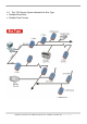
1.4 The 7000 Series System Network for Bus Type • Multiple Baud Rate • Multiple Data Format 7000 Bus Converter User’s Manual (Version 1.
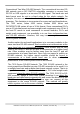
Conventional Two-Wire RS-485 Network: The conventional two-wire RS485 network uses a DIP SWITCH selectable converter to convert host RS-232 or USB signals to a two-wire RS-485 signal. The baud rate and data format must be set to a fixed value for the whole network. For example, the user can choose baud rate=9600 and data format=10 bit per character. This limitation is inconvenient for some real world applications.
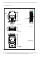
7000 Dimension 29.50 8 2-SCREW M3 7.30 56.00 88.50 35.30 O4.5X4 25.00 40.50 33.00 Back View 72.00 Side View 25.00 33.00 Top View 10.50 50.00 56.00 111.00 1.5 58.50 72.00 From View 7000 Bus Converter User’s Manual (Version 1.
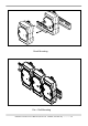
Stack Mounting Din – Rail Mounting 7000 Bus Converter User’s Manual (Version 1.
2. I-7520/A/R/AR, PCISA-7520AR, PCISA-7520R 2.1 I-7520: 2.1.
2.2 I-7520R: 2.2.
2.3 I-7520A: 2.3.
2.3.3 The I-7520A has three different output types Selecting the I-7520A output type. NOTE: The RS-422 and RS-485 output types couldn’t be used simultaneously, which means that you can only select 1 type to output. Type 1: 1-channel RS-485 output. Type 2: 1-channel RS-422 output. Type 3: 2-channel RS-485 output. (Support star network) RS422/485 Output Jumpers settings: For type 1: Set the JP1 jumper to positions 2 and 3. For type 2: Set the JP1 jumper to positions 2 and 3.
2.4 I-7520AR : 2.4.
2.4.3 The I-7520AR has three different output types Selecting the I-7520AR output type. NOTE: The RS-422 and RS-485 output types couldn’t be used simultaneously, which means that you can only select 1 type to output. Type 1: 1-channel RS-485 output. Type 2: 1-channel RS-422 output. Type 3: 2-channel RS-485 output. (Support star network) RS422/485 Output Jumpers settings: For type 1: Set the JP1 jumper to positions 2 and 3. For type 2: Set the JP1 jumper to positions 2 and 3.
2.5 PCISA-7520AR Pin Assignment and Specification: CN1 1 6 2 7 3 8 4 9 5 RXD TXD GND DB9M FEMALE CN2 CN2 5 9 4 8 3 7 2 6 1 5 9 4 8 3 7 2 6 1 DD+ DD+ RX+ RXRX+ RXTXTX+ TXTX+ DB9S MALE DB9S MALE RS-485 ( D+, D- ) RS-422 ( RX+, RX-, TX+, TX- ) CON2: RS-485/422 DB9 Male Connector Terminal 2-wire RS-485 4-wire RS-422 1 DATA+ TX+ 2 3 Not Connect 4 Not Connect RX+ 5 6 DATATX7 8 Not Connect RX9 The PCISA-7520AR is exactly the same as 7520AR except for the PCI and ISA interface.
2.6 PCISA-7520R Pin Assignment and Specification: CN1 DCD DSR RXD RTS TXD CTS DTR 1 6 2 7 3 8 4 9 5 GND DB9M FEMALE CN2 5 9 4 8 3 7 2 6 1 DD+ DD+ DB9S MALE RS-485 ( D+, D- ) CON2: RS-485 DB9 Male Connector Terminal 2-wire RS-485 1 DATA+ 2 3 Not Connect 4 5 6 DATA7 8 Not Connect 9 The PCISA-7520R is exactly the same as 7520R except for the PCI and ISA interface. It is designed for easy installation. 7000 Bus Converter User’s Manual (Version 1.
2.7 Basic Wire Connection for I-7520: RS 485 wire connection. GND ÅÆ Ext. Power GND +VS Å Æ Ext.
2.8 How to select 7520 / 7520R The 7520R is exactly the same as 7520 except for the isolation site. The isolation site of the 7520 is located in the RS-232 interface circuit, but the isolation site of the 7520R is located in the RS-485 interface circuit.
Note: the power ground of q7000 and rRS-485 is common ground. This is the same for Adam 4000, Nudam 6000 and DATAFORTH 9B series modules. In most applications, the p7520 are used to convert the oRS-232 signal to rRS-485 network. Normally the p7520 does not use the same DC power ground as the nHost PC/PLC, and the isolation site is in the RS-232 section. Therefore the nHost PC/PLC is isolated from rRS-485 network.
WARNING!! ERROR CONDITION 2: if the p7520 uses the same DC power ground with nHost PC/PLC (for example, nHost PC/PLC provide non-isolated DC power source to p7520). In this situation, (1) The nHost PC/PLC is common ground with power ground of p7520 (2) The power ground of p7520 is common ground with rRS-485 Therefore the nHost PC/PLC is common ground with rRS-485 network. That is to say, there is no isolation between nHost PC/PLC and rRS-485 network.
The 7520R is designed for PLC networking. During normal conditions, the PLC system will have a stable DC-24V power source. The user may use this power source to s7520R(configuration A). When using t7520, the user must use another power source, uPWR-24 (configuration B). The isolation feature is very important in real world applications, therefore the user should pay attention when selecting the correct module.
3. USB series: I-7560 / I-7561 / I-7563 What is USB? USB, or Universal Serial Bus is a connectivity specification developed by computer and telecommunication industry members for attaching peripherals to computers. USB is designed to free all the troubles when installing external peripherals. It eliminates the hassle to open computer case for installing cards needed for certain devices.
3.1 I-7560 Pin Assignment and Specifications: Introduction The I-7560 adds a Windows serial Com port via its USB connection and is compatible with new & legacy RS-232 devices. USB Plug and Play allows easy serial port expansion and requires no IRQ, DMA, or I/O port resources. I-7560 features a full set of RS-232 modem data and control signals (TxD, RxD, RTS, CTS, DSR, DTR, DCD, RI, and GND) on its PC compatible DB9 male connector. It also features a high-speed 115.2 Kb/s transmission rate.
3.1.1 The I-7560 System Network Configuration: 3.1.2 Block Diagram: 7000 Bus Converter User’s Manual (Version 1.
3.1.3 I-7560 Driver Installation Installing the Device This section will guide you on how to install the I-7560 USB to RS-232 converter under Windows XP, Windows 2000, Windows ME, and Windows 98 operating systems. (No support for WinNT). Download driver files from 1. Package CD, \Napdos\7000\756x\7560 2. ftp://ftp.icpdas.com/pub/cd/8000cd/napdos/7000/756x/7560 The following steps will show how to install the device under Windows 2000.
4. An “Install Hardware Device Drivers” window is shown. Click “Next” to initiate a search for a suitable driver for your device. 5. Select the “Specify a location” optional search locations. If the “CD-ROM drives” checkbox is selected, please insert the driver CD. Click “Next” to start the search. 7000 Bus Converter User’s Manual (Version 1.
6. If the “Specify a location” is selected, you much choose the correct path. Enter E:\Napdos\7000\756x\7560(The ‘E’ is the Disk that Package CD put in). Click “OK” to start the search. 7. Once Windows finds the correct driver, click “Next” to install the driver. 7000 Bus Converter User’s Manual (Version 1.
8. Windows will then install the driver for the USB-to-Serial COM Port. Once installation is complete, Windows will notify you that it has finished installing the software. Click “Finish” to continue. NOTE: When you finish the driver installation, please unplug the USB cable, and then plug the USB cable again. 7000 Bus Converter User’s Manual (Version 1.
3.1.4 Verifying the Installation: This section will show you on how to verify whether the I-7560 was properly installed. You will also need to determine the COM port assignment made by Windows for the USB to RS-232 converter. Note: Before you connect the I-7560 for the first time, ensure that you do not attach any serial devices to the converter. You must only connect the I-7560 itself. To verify whether the device is properly installed and determine the COM port assignment for the device: 1.
2. If you need to reassign the COM Port name to another Port number, you can double-click on the device (I-7560 USB-to-RS232) to view the properties. (The I-7561 cannot reassign the COM Port name to another Port number under Win98 and Win98SE.) 3. Once the properties window opens click on the Port Settings tab. Then click on the advanced button. 7000 Bus Converter User’s Manual (Version 1.
4. The Advanced Settings dialog box will now be displayed. Click on the COM Port Number drop down box to check what other port numbers are available. If, for instance, Windows has assigned COM5 to the device, you may try to reassign it to a lower unused port number. Click OK when finished. Try running HyperTerminal to test whether the new port number is OK. Note: Some software programs may only support Ports up to COM4 and may not work if the port is assigned to COM5 or higher. 5.
3.1.5 Uninstalling the Device Driver It is easy to uninstall the USB to Serial device driver: 1. Run the DRemover98_2K.exe Uninstall program which can be found on the Package CD, \Napdos\7000\756x\7560 or at ftp://ftp.icpdas.com/pub/cd/8000cd/napdos/7000/756x/7560 2. The uninstall program will then prompt you whether you want to remove the utility program. Click “ OK “ to continue. 3. After the uninstall is complete, the program will prompt you to restart Windows. Click “ Yes ” to continue. 4.
3.2 I-7561 Pin Assignment and Specifications Introduction The I-7561 is a cost-effective module for transfer serial data over USB. It allows you to connect your serial devices to systems using a USB interface. Connecting the I-7561 to a PC, you get one extra high-speed RS-232/422/485 ports. Like our I-7520A, the I-7561 contains “ Self Tuner “ This chip auto-tunes the baud rate and data format to the RS-485 network.
3.2.1 The I-7561 System Network Configuration: • Multiple Baud Rate • Multiple Data Format 3.2.2 The I-7561 Block Diagram: 7000 Bus Converter User’s Manual (Version 1.
3.2.3 I-7561 has four different output types. Selecting the I-7561 output type. NOTE: The RS-232, RS-422 and RS-485 output types couldn’t be used simultaneously, which means that you can only select 1 type to output. Type 1: 1-channel RS-485 output. Type 2: 1-channel RS-422 output. Type 3: 2-channel RS-485 output. (Support star network) Type 4: 1-channel RS-232 output. RS422/485 Output Jumpers settings: For type 1: Set the JP3 jumper to positions 2 and 3. For type 2: Set the JP3 jumper to positions 2 and 3.
3.2.4 I-7561 Driver Installation Installing the Device This section will guide you on how to install the I-7561 USB to RS-232/422/485 converter under Windows XP, Windows 2000, Windows ME, and Windows 98 operating systems. (No support for WinNT). Download driver files from 1. Package CD, \Napdos\7000\756x\7561 2. ftp://ftp.icpdas.com/pub/cd/8000cd/napdos/7000/756x/7561 The following steps will show how to install the device under Windows 2000.
4. An “Install Hardware Device Drivers” window is shown. Click “Next” to initiate a search for a suitable driver for your device. 5. Select the “Specify a location” optional search locations. If the “CD-ROM drives” checkbox is selected, please insert the driver CD. Click “Next” to start the search. 7000 Bus Converter User’s Manual (Version 1.
6. If the “Specify a location” is selected, you much choose the correct path. Enter E:\Napdos\7000\756x\7561(The ‘E’ is the Disk that Package CD put in). Click “OK” to start the search. 7. Once Windows finds the correct driver, click “Next” to install the driver. 7000 Bus Converter User’s Manual (Version 1.
8. Windows will then install the driver for the USB-to-RS232/422/485. Once installation is complete, Windows will notify you that it has finished installing the software. Click “Finish” to continue. NOTE: When you finish the driver installation, please unplug the USB cable, and then plug the USB cable again. 7000 Bus Converter User’s Manual (Version 1.
3.2.5 Verifying the Installation: This section will show you on how to verify whether the I-7561 was properly installed. You will also need to determine the COM port assignment made by Windows for the USB to RS-232/422/485 converter. Note: Before you connect the I-7561 for the first time, ensure that you do not attach any serial devices to the converter. You must only connect the I-7561 itself. To verify whether the device is properly installed and determine the COM port assignment for the device: 1.
2. If you need to reassign the COM Port name to another Port number, you can double-click on the device (I-7561 USB-to-RS232/422/485) to view the properties. (The I-7561 cannot reassign the COM Port name to another Port number under Win98 and Win98SE.) 3. Once the properties window opens click on the Port Settings tab. Then click on the advanced button. 7000 Bus Converter User’s Manual (Version 1.
4. The Advanced Settings dialog box will now be displayed. Click on the COM Port Number drop down box to check what other port numbers are available. If, for instance, Windows has assigned COM5 to the device, you may try to reassign it to a lower unused port number. Click OK when finished. Try running HyperTerminal to test whether the new port number is OK. Note: Some software programs may only support Ports up to COM4 and may not work if the port is assigned to COM5 or higher. 5.
3.2.6 Uninstalling the Device Driver It is easy to uninstall the USB to Serial device driver: 1. Run the DRemover98_2K.exe Uninstall program which can be found on the Package CD, \Napdos\7000\756x\7561 or at ftp://ftp.icpdas.com/pub/cd/8000cd/napdos/7000/756x/7561 2. The uninstall program will then prompt you whether you want to remove the utility program. Click OK to continue. 3. After the uninstall is complete, the program will prompt you to restart Windows. Click “Yes” to continue. 4.
3.3 I-7563 Pin Assignment and Specifications: Introduction The I-7563 is a cost-effective module for transfer serial data over USB. It allows you to connect your serial devices to systems using a USB interface. Connecting the I-7563 to a PC, The I7563 contains “ Self Tuner “ This chip auto-tunes the baud rate and data format to the Rs-485 network. The I-7563 module derives the power from the USB port and doesn’t need any power adapter. It also features a high-speed 115.
3.3.1 The I-7563 System Network Configuration: • Multiple Baud Rate • Multiple Data Format 3.3.2 The I-7563 Block Diagram: 7000 Bus Converter User’s Manual (Version 1.
3.3.3 I-7563 Driver Installation This section will guide you on how to install the I-7563 USB to 3 Ports RS-485 Hub under Windows XP, Windows 2000, Windows ME, and Windows 98 operating systems. (No support for WinNT). Download driver files from 1. Package CD, \Napdos\7000\756x\7563 2. ftp://ftp.icpdas.com/pub/cd/8000cd/napdos/7000/756x/7563 The following steps will show how to install the device under Windows 2000. Basically, the procedures are also somewhat the same for other Windows operating systems. 1.
4. An “Install Hardware Device Drivers” window is shown. Click “Next” to initiate a search for a suitable driver for your device. 5. Select the “Specify a location” optional search locations. If the “CD-ROM drives” checkbox is selected, please insert the driver CD. Click “Next” to start the search. 7000 Bus Converter User’s Manual (Version 1.
6. If the “Specify a location” is selected, you much choose the correct path. Enter E:\Napdos\7000\756x\7563(The ‘E’ is the Disk that Package CD put in). Click “OK” to start the search. 7. Once Windows finds the correct driver, click “Next” to install the driver. 7000 Bus Converter User’s Manual (Version 1.
8. Windows will then install the driver for the USB-to-3 Ports. Once installation is complete, Windows will notify you that it has finished installing the software. Click “Finish” to continue. NOTE: When you finish the driver installation, please unplug the USB cable, and then plug the USB cable again. 7000 Bus Converter User’s Manual (Version 1.
3.3.4 Verifying the Installation: This section will show you on how to verify whether the I-7563 was properly installed. You will also need to determine the COM port assignment made by Windows for the USB to 3 Ports RS-485 Hub. Note: Before you connect the I-7563 for the first time, ensure that you do not attach any serial devices to the converter. You must only connect the I-7560. To verify whether the device is properly installed and determine the COM port assignment for the device: 1.
2. If you need to assign the COM Port name to another Port number, you can double-click on the device (I-7563 USB-to-RS485 Hub) to view the properties. (The I-7563 cannot reassign the COM Port name to another Port number under Win98 and Win98SE.) 3. Once the properties window opens click on the Port Settings tab. Then click on the advanced button. 7000 Bus Converter User’s Manual (Version 1.
4. The Advanced Settings dialog box will now be displayed. Click on the COM Port Number drop down box to check what other port numbers are available. If, for instance, Windows has assigned COM5 to the device, you may try to reassign it to a lower unused port number. Click OK when finished. Try running HyperTerminal to test whether the new port number is OK. Note: Some software programs may only support Ports up to COM4 and may not work if the port is assigned to COM5 or higher. 5.
3.3.5 Uninstalling the Device Driver It is easy to uninstall the USB to Serial device driver: 1. Run the DRemover98_2K.exe Uninstall program which can be found on the Package CD, \Napdos\7000\756x\7563 or at ftp://ftp.icpdas.com/pub/cd/8000cd/napdos/7000/756x/7563 2. The uninstall program will then prompt you if you want to remove the utility program. Click OK to continue. 3. After the uninstall is complete, the program will prompt you to restart Windows. Click “Yes” to continue. 4.
4. I-7551 : RS-232 to RS-232 Converter 4.1 I-7551 Pin Assignment and Specifications: Introduction The I-7551 Photo coupler provides a complete full-duplex (including control signal) electrical isolation channel between two RS-232 devices. This isolation is an important consideration if a system uses different power sources, has noisy signals or must operate at different ground potentials. The I-7551 has the option of reconfiguring which control signal is used.
4.1.1 The I-7551 System Network Configuration: • Multiple Baud Rate • Multiple Data Format 4.1.2 The I-7551 Block Diagram: 7000 Bus Converter User’s Manual (Version 1.
4.1.3 I-7551 has two different output types. Selecting the I-7551 output type. NOTE: The type1 and type2 couldn’t be used simultaneously, which means that you can only select 1 type to output. Type 1: Input :TxD, RxD, CTS, RTS, GND. Output :TxD, RxD, CTS, RTS, GND. Type 2: Input :TxD, RxD, DSR, DTR, GND. Output : TxD, RxD, DSR, DTR, GND. Type1 and Type2 Jumpers settings: NOTE: RXD and TXD are permanent setting. For type 1: Set the JP1 jumper to positions 2 and 3. Set the JP2 jumper to positions 2 and 3.
5. Repeater series: I-7510 / I-7510A / I-7510AR / I-7513 5.1 I-7510: 5.1.1 Pin Assignment and Specifications: 7510: RS-485 Repeater • Input: two-wire RS-485, (D+, D-) • Output: two-wire RS-485, (D+, D-) • Speed: “Self Tuner” inside, auto switching baud rate, from 300 to 115200 BPS • Isolation voltage: 3000V • Connector: plug-in screw terminal block • Power requirements: +10V dc ~ +30V dc • Power consumption: 2.2W(Max) 5.1.2 Block Diagram: 7000 Bus Converter User’s Manual (Version 1.
5.2 I-7510A: 5.2.1 Pin Assignment and Specifications: 7510A: RS-485/RS-422 Repeater • Input: RS-485/RS-422 • Output: RS-485/RS-422 • Speed: “Self Tuner” inside, auto switching baud rate, from 300 to 115200 bps • Isolation voltage: 3000V • Connector: plug-in screw terminal block • Power requirements: +10V dc ~ +30V dc • Power consumption: 2.2W(Max) 5.2.2 Block Diagram: 7000 Bus Converter User’s Manual (Version 1.
5.3 I-7510AR: 5.3.1 Pin Assignment and Specifications: Introduction ( RS-485 ) ( RS-422 ) I-7510AR RS-422/485 Repeter Variable Baud Rate 300,..9600,..115.2K Variable Rate Format ( RS-485 ) I-7510AR is exactly the same as I-7510A except for the isolation site, The isolation site of I-7510A is located in the input interface circuit, but the isolation site of the I-7510AR is located in the input and output interface circuit. In other words, I-7510AR is three- way isolation repeater module.
5.3.2 System Network Configuration: • Multiple Baud Rate • Multiple Data Format 5.3.3 Block Diagram: 7000 Bus Converter User’s Manual (Version 1.
5.4 I-7513: 5.4.1 Pin Assignment and Specifications: Introduction ( CH 1 ) ( CH 2 ) I-7513 RS-485 HUB One channel RS-485 Input Three channels RS-485 Output ( CH 3 ) I-7513 is one channel RS-485 with a three way Active Star Wiring Hub. The unit has 3 independent RS485 output channels each with their own driver, which can transmit signals along 4,000 ft (1.2Km). Of cable on each channel. I-7513 includes both Hub and Repeater function. So each output channel can be connected anther hub.
5.4.2 System Network Configuration: • Multiple Baud Rate • Multiple Data Format 5.4.3 Block Diagram: 7000 Bus Converter User’s Manual (Version 1.
5.5 Basic Wire Connections for I-7510 (1) Extends RS-485 network if the path is over 4000 ft or 1.2 Km (2) Extends RS-485 network if connecting over 256 modules (3) Cuts a long RS-485 path into several isolated short RS-485 paths for protection 7000 Bus Converter User’s Manual (Version 1.
6. 7000 RS-485 Networking 6.1 Standard/Isolation Configuration Daisy-Chain Configuration. The Host PC/PLC will send out a command string from its RS-232 port. The s7520 will convert these RS-232 signals into a RS-485 signal and isolate the host from qRS-485 network. The 7000 series modules, including D/I, D/O, A/D, D/A, Timer/Counter and MMI modules, will be directly connected to qRS-485. These 7000 series modules can connect a max. Of 256 modules to the qRS-485 network without a repeater, the 7510.
o7xxx=module address 01, baud rate=9600 p7xxx=module address 01, baud rate=115200 These three modules can share the same RS-485 network, generated by s7520. (4) Therefore there is 256*8=2048 modules max. In one RS-485 network with a repeater (7510). The “search function” given in DCON_DOS can search for all these 2048 modules in one RS-485 network. Refer to “DCON_DOS.pdf” for completely source listing of “search function”. When the RS-485 network is over 4000 ft or 1.
For example, the q7510, s7510 are used to isolate local modules from nRS-485 network. If there is high energy transient on nRS-485 network, all the local modules will be safe. Isolation Configuration (Strongly Recommended): If the RS-485 network is not over 100 meters, the terminated resistors are not needed. However, it may be necessary to insert two terminated resistors at both end of the RS-485 segment. It is not easy to calculate the value of a terminator resistor.
It is recommended to use the “trial and error” rule. The trial and error rules are given as follows: (1) If the length of RS-485 is about 1.2 Km, try 330Ω first (2) Run TEST.EXE of DCON_DOS Select function_5, run continuously for at least 8 hours to make sure communication is OK. (3) If function_5 finds many communication errors, use an oscilloscope to check the waveform. The waveform will tell you whether the terminator is too small or too big. Then adjust your terminator and run TEST.EXE again.
6.2 PLC Networking Applications These PLCs can be used at different baud rates & different configurations. For example, PLC-1=1 start + 7 data + 1 stop=9-bit/byte, baud rate=1200 PLC-n=1 start + 8 data + 1 parity + 1 stop=11-bit/byte, baud rate=9600 PLC-m=1 start + 8 data + 1 parity + 2 stop=12-bit/byte, baud rate=115200 OMRON CQM1 = 1 start + 7 data + 1 even parity + 2 stop =11-bit/byte OMRON C200 = 1 start + 7 data + 1 even parity + 2 stop = 11-bit/byte The n7520 can be the 7520 or 7520R, refer to Sec.
6.3 PC Networking Applications: (For this application, we recommend to use i-7520U to replace the i-7520) Every remote-PC must have a unique address. This unique address is similar to the module address of the 7000 series. We call it a “slave-PC address”. The module address of the 7000 series is limited to 256, but the slave-PC address is unlimited. The user can connect thousands of PCs in one RS-485 network by using a repeater, the 7510. Refer to “DCON_DOS.pdf” for software details.
6.4 RS-232 Devices Network (For this application, we recommend to use i-7520U to replace the i-7520) Some RS-232 devices can be connected to the 7000 RS-485 network very easily, just like the PC or PLC introduced in Sec 6.2 and Sec. 6.3. These RS-232 devices must adhere to 3 rules given as follows: Rule 1: cannot send out the RS-232 signal in normal, operating state.