Installation Instructions SINGLE PACKAGE AIR CONDITIONERS PAF & APFM Series - 2 to 5 TON 519 01 1102 O0 Printed in U.S.A.
Safety Labeling and Signal Words Danger Label Danger, Warning and Caution White lettering on a black background except the word DANGER which is white with a red background, The signal words DANGER, WARNING and CAUTION are used to identify levels of hazard seriousness. The signal word DANGER is only used on product labels to signify an immediate hazard. The signal words WARNING and CAUTION will be used on product labels and throughout this manual and other manuals that may apply to the product.
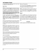
2 TO 5 TON 41/2 . See Detail BASE PAN - CHASSIS 42-3/4"* © BASE RAIL BASE RAIL 46-1/8"* 12-1/4 -- Condensate Drain 19 SUPPLY 12-1/4 RETURN 19 1-9/16 2-3/16 2- 3/16 3-3/4 A B C D E F G H I 2 TO 3-1/2 Ton UNIT SIZE 29-1/2 47-1/2 47-1/2 3 9-1/2 12 14 12 14 4-1/2 4 TO 5 Ton 37-1/2 47-1/2 47-1/2 4 6-1/2 19 19 12 12 4-1/2 J ** Measured from inside to inside on base rails.
Minimum Clearances to Combustible SAFE INSTALLATION Condenser Blower Control Service Service Clearance Installation or repairs made by unqualified B149-1 (Side) Side Combustible 30" .............................. ............................... 30" 30" 3 Ft. Overhang and Top of Unit ........................ 30" Base (Wood or Class roof covering A, B or C material) .................... 0" and CSA FIGURE The information ...................................
Rooftop Installation Rooftop platform requirements: - The unit MUST be situated to provide safe access for servicing. - The existing roof structure MUST be adequate to support the weight of the unit or the roof MUST be reinforced. Check the weight of the unit in relation to the roof structure and local building codes or ordinances and reinforce roof structure if necessary. See the last page of this manual for unit weights. outlet from trap MUST be at least 1" (25.4mm) below top of outlet from unit.
All exposed wiring and connections MUST be made with weatherproof cable or wire unless installed in conduit. Thermostat The location of the thermostat has an important effect on the operation of the unit. FOLLOW THE INSTRUCTIONS INCLUDED WITH THE THERMOSTAT FOR CORRECT LOCATION, MOUNTING AND WIRING. Ground Connections A ground lug is installed on the control plate for the ground connection (see FIGURE 3).
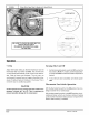
FIGURE3 [ Control Box Low Voltage Terminal Connections Capacitor Control Board Contactor Transformer 51901 110200 L_J
Air DistributionSystem For airflow data (blower performance data, blower speed tap settings, etc.) see the Parts List. Ductwork Connections The use of flexible, non-combustible connectors between main trunk ducts and supply and return air plenums is recommended to minimize vibration transmission. Ductwork NOTE: The total heat gain!heat loss from the structure as expressed in total Btu/hr MUST be calculated by manufacturer's method or in accordance with "A.S.H.R.A.E.
Start-up Procedures the Parts List for the desired speed tap to achieve the required CFM for the applicable model. Electrical shock hazard. Use extreme care during checks and procedures. all of the following Make sure electric power is turned instructed in appropriate steps. OFF as Failure to follow this warning can result in property damage, personal injury, and/or death. Circulating Determining 1. 2.
Blower Motor Speed Taps (3-Speed and 4-Speed Motors) / ,/ / YELLO_L SPEED DATA IN UNITS TECHNICAL INFORMATION LABEL I BE SURE TO CHECK BLOWER MOTOR I ON THE UNIT f Operation Turning Cooling Adjust thermostat setting to desired temperature and set thermostat Heat-Cool switch to COOL. The unit will come Set the thermostat selector switch to OFF and set the fan switch to AUTO. To restart, set thermostat selector switch to COOL and set thermostat to temperature desired.
Adjusting Room Temperatures FIGURE 5 1 Typical Branch Duct Dampers If the temperature in individual rooms is not as desired, balance the system by adjusting the dampers in the branch ducts. Adjust a little at a time and wait a day after each change to judge the effect. Once the dampers are adjusted for normal weather conditions, it is best to leave them that way. Compensate for temporary weather changes by adjusting the thermostat setting.
Cleanthesurrounding areaandthecondenser andevaporatorcoils.Usecautiontoavoiddamagetocoilfins.Donot usean acid-basedcleaneron coatedfin material. Blower Motor FIGURE 8 1 Wire Colors Access To remove the blower motor and/or the blower motor housing assembly, remove the blower access panel. Refer to FIGURE 7 for a view of blower motor and compartment, FIGURE 7 I Blower Motor and Housing Circulating Air Blower Visually inspect the blower wheel for accumulations of dirt or lint.
INTERNATIONAL COMFORT PRODUCTS LIMITED WARRANTY CERTIFICATE For Cooling SAVE THIS CERTIFICATE. province It gives you specific & Heating Products legal rights, and you may also have other rights which may vary from state to state and to province. If your unit needs servicing, contact a qualified dealer or qualified service technician of your choice. When requesting service, please have the model and serial number from each unit in your heating and/or cooling system readily available.
ADDITIONAL TERMS FOR RESIDENTIAL APPLICATIONS ONLY The Additional Terms for the components listed below are in addition to, and subject to, the General Terms on the reverse side of this page. Warranty coverage is limited to parts that fail due to defect in materials or workmanship during the specified term. CENTRAL GAS & OIL FURNACE HEAT EXCHANGERS* Gas Model Series: C9MPV. HgMPV. TgMPV. CgMPT. H9MPT. T9MPT. C9MPD. HgMPD. TgMPD: Limited Lifetime Warranty on heat exchangers.