
Manual


Start-up Procedures
Electrical shock hazard.
Use extreme care during all of the following
checks and procedures.
Make sure electric power is turned OFF as
instructed in appropriate steps.
Failure to follow this warning can result in prop-
erty damage, personal injury, and/or death.
Circulating Air Blower
Determining Blower Speed
1. Turn electric power OFF,
2.
From the system design, determine the external static
pressure (ESP) for the supply ducts, return ducts and
registers, diffusers, grilles, dampers, heaters and fil-
ters.
3. To your system ESP determined in Step 2, add 0.05
In. W.C. for a wet coil.
4. From the system design, determine the desired cool-
ing airflow in cubic feet per minute (CFM).
5, Locate the unit's Blower Performance Data table in
the tech data sheet for the unit's voltage. (The tech
data sheet is attached to the inside of the electrical ac-
cess panel and is also published in the Parts List.)
From the table, determine the speed tap the desired
airflow requires.
6. See next section, Speed Taps, to set the blower motor
speed terminal block (speed taps) determined in the
following steps.
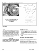
Speed Taps
After determining the required CFM and speed tap data
from the tech data sheet, follow the steps below to change
speeds if necessary.
NOTE: The yellow lead MUST always be connected to the
speed tap block at the common quick connect terminal. The
terminal is identified as COM. Also, this is the only lead
which is 3/16" wide. All other quick connects are 1/4"wide.
Refer to the unit's wiring diagram, which is attached to the
inside of the electrical access panel and is also published in
the Parts List for the desired speed tap to achieve the re-
quired CFM for the applicable model.
Cooling, Heating (Heat Pump) and Auxiliary
Electric Strip Heat
NOTE: The cooling, heat pump and strip heat airflows
are all on the same speed tap. The refrigerant system
requires the same specific CFM for proper operation in
the cooling and the heat pump mode. For this reason,
cooling and heating airflow must be the same. DO NOT
SPLITOUT INTO A COOLING SPEED AND HEATING
SPEED.
Check Before Starting
2,
3,
4,
Check that the blower motor speed terminal block is
set to the proper speed. Refer to the unit wiring dia-
gram and the Technical Labels in the Parts List.
Check to see that clean, properly sized field supplied
air filters are installed in the return air duct.
Inspect the inside of the unit to be sure that all wires
are in place and all tools, etc. are removed.
Replace all service access panels.
Check the unit's operation as outlined in the following
instructions. If any unusual sparking, odors or noises are
encountered, shut OFF electric power immediately. Re-
check for wiring errors, or obstructions in or near blower
motors.
Sequence of Operation
Cooling Mode: Energized (R,G,Y1)
(a) When high and low voltage is initially applied
to unit:
(1)
(2)
On a call for cooling ......... :
The compressor and condenser fan will energize im-
mediately. The evaporator blower motor will energize
immediately.
When the cooling setpoint has been satis-
fied ......... :
The compressor and condenser fan will de-energize
immediately. The evaporator blower motor will have a
delay off and will de-energize after 30 seconds.
51901 110200 191