
Manual

7. Start-up Procedures
Electrical shock hazard.
Use extreme care during all of the following checks and pro-
cedures.
Make sure electric power is turned OFF as instructed in ap-
propriate steps.
Failure to follow this warning can result in property damage,
personal injury, and/or death.
Final Electrical Check
Makeafinalwiringchecktobesuresystemiscorrectlywired.Inspectfieldinstalledwiring
andtheroutingtoensurethatrubbingorchafingdue tovibrationwillnot occur.
NOTE:WiringMUSTbe installedso it is protectedfrompossiblemechanicaldamage.
Circulating Air Blower
DeterminingBlowerSpeed
1.Turn electric power OFF.
2. From the system design, determine the total external static pressure
(ESP) for the supply ducts, return ducts and registers, diffusers,
grilles, dampers, heaters and filters.
3.To your system ESP determined in Step 2, add 0.05 In. W.C. for a
wet coil.
4. From the system design, determine the desired cooling airflow in
cubic feet per minute (CFM).
5. Locate the unit's Blower Performance Data table on the tech data
label for the unit's voltage. (The tech data sheet is attached to the
evaporator access panel on the unit.) From the table, determine the
speed tap required to achieve the desired airflow.
&See next section, Speed Taps, to set the blower motor speed termi-
nal block (speed taps) to the cooling speed determined in the pre-
vious steps.
I
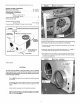
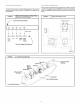
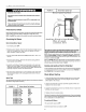
FIGURE 18 I Blower Motor
Speed Taps
I
BIow'er Speed Tap Block
Auxiliary E_ectric Heat B
Wire (if used)
connects here
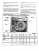
BE SURE TO CHECK BLOWER MOTOR SPEED DATA ON THE
UNITS TECHNICAL DATA LABEL LOCATED ON THE UNIT.
NOTE: Electric heater blower wire may be attached to any "Appropriate"
speed tap See FIGURE 11 notes. The yellow lead MUST always be con-
nected to the speed tap block at the common quick connect terminal. The
terminal is identified as COM.
Refer to FIGURE 18 and the appropriate unit wiring diagram included in
this manual. Wire the black wire to the required speed tap terminal to
achieve required airflow determined in Step 5.
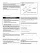
Cooling and Auxiliary Electric Strip Heat
On Air Conditioning units with electric heat, the heat strip may be operated
on a lower blower speed than cooling (Refer to Heater Chart FIG URE 11)
See FIGURE 15 for connection location.
Check Before Starting
SpeedTaps
AfterdeterminingtherequiredCFMandspeedtap datafromthetechdatasheet,followthe
steps belowto change speedsif necessary.
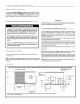
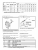
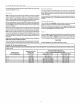
FIGURE 17 [ Blower Speed Tap Settings
10 SEER 2 TON MED
10 SEER 21/2 TON MED
10 SEER 3 TON LOW
10 SEER 31/2 TON MED HI
10 SEER 4 TON LOW
10 SEER 5 TON HI
12 SEER 2 TON MED
12 SEER 21/2 TON MED
12 SEER 3 TON LOW
12 SEER 31/2 TON MED HI
12 SEER 4 TON LOW
1. Check that the blower motor speed terminal block is set to the prop-
er cooling speed. Refer to the unit wiring diagram and the various
airflow tables in this manual.
2. Check to see that clean, properly sized field supplied air filters are
installed in the return air duct.
3. Inspect the inside of the unit to be sure that all wires are in place and
all tools, etc. are removed.
4. Replace all service access panels.
Checktheunit'soperationasoutlinedinthe followinginstructions.If anyunusualsparking,
odorsornoisesareencountered,shutOFFelectricpowerimmediately.Recheckforwiring
errors,orobstructionsin ornear blower motors.
CirculatingAir Blower
1. Be sure electric power is OFF.
2. Set thermostat Heat-Cool selector to OFF.
10