
Manual

1. Safetv Labelinq and Siflnal Words
Danger,Warningand Caution
ThesignalwordsDANGER,WARNINGand CAUTIONareusedto identifylevels of haz-
ard seriousness.The signalword DANGERis onlyusedon productlabelsto signify an
immediatehazard.The signalwords WARNINGand CAUTIONwill be used on product
labelsand throughoutthis manualand other manualsthat mayapplyto the product.
2. Safe Installation Requirem ents
CAUTION
Do NOToperate unit in a corrosive atmosphere containing chlorine,
fluorine, or any other corrosive chemicals.
Installation or repairs made by unqualified persons can result
in hazards to you and others. Installation MUST conform with
local building codes or, in the absence of local codes, with the
National Electrical Code NFPA70-1990 or current edition.
The information contained in this manual is intended for use
by a qualified service technician familiar with safety proce-
dures and equipped with the proper tools and test instru-
ments.
Failure to carefully read and follow all instructions in this
manual can result in unit malfunction, property damage, per-
sonal injury and/or death.
• Seal supply and return air ducts.
• Check to see that filters are installed correctly and are the proper
type and size.
NOTE:Itisthepersonalresponsibilityandobligationofthecustomertocontacta qualified
installerto ensurethat the installationisadequateand conformsto governingcodes and
ordinances.
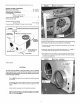
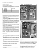
3. Locatinq & Installinq The Unit
The unitis designedfor outdoorinstallationonly.Placethe unit on a platformatground
level. The unitmay beinstalledon a concreteslab of 48" (1219mm)x 48" (1219mm)
dimensions. Cement blocks on a 3" sand footing willalso work. The slab or blocks
SHOULDNOT be in contactwith any partofthe structure. Checklocalcodescovering
zoning,noise, platforms,etc..
Ifpracticalavoid locatingnextto freshair intakes,ventorbedroomwindows. Noisemay
carry intothe openingsand disturbpeopleinside.
Avoid installationsunderroofoverhangswithoutguttering. Waterdrainingfrom the roof
ontotheunitcould produceexcessivenoise,and maycauseiceto buildup on coil orfan.
Placementofthe unitshouldbe ina welldrainedareaorthe unit MUSTbe supportedhigh
enoughso runoffwillnotenter the unit.
Do not locate unitwhereheat, lint orexhaustfumeswill be dischargedon unit (asfrom
dryervents.)
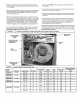
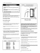
Clearances
Minimum clearances,as specified in FIGURE 1, MUST be maintainedfrom adjacent
structuresto provideadequateair circulationand roomfor service personnel.
While minimumclearancesare acceptablefor safety reasons,theymay not allowade-
quateaircirculationaroundthe unitforproperoperation.Wheneverpossible,it isdesirable
to allow additionalclearance,especiallyaroundthe condenserinlet and dischargeopen-
ings.
Do NOTinstallthe unitin arecessedor confinedareathat will permitdischargedair from
the condensertorecirculateto the condenserinlet.
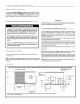
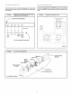
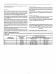
Dimensions
NOTE: DUCT COLLARS ATTACHED TO SUPPLY AND RETURN MUST BE REVERSED AT INSTALLATION. SEE INSTRUCTIONS ON PAGE 3.
ALL DIMENSIONS IN iNCHES ROUND SHAPED FLANGE WiLL
ACCOMMODATE 12" DIA.
SUPPLY DUCT
t
26.5
COIL
ACCESS
PANEL
ROUND FLANGE
WILL
ACCOMMODATE
14_ DIA.
RETURN DUCT
T m
10
\ 41
CONDENSATE DRAIN
CONECTION
* ELECTRICAL ACCESS FOR LINE VOLTAGE POWER SUPPLY-ONE FOR UNIT, ONE FOR HEATER
** FOR LOW VOLTAGE WIRING
DIA HOLE**
_/4 DIA.*
_/4 DIA.*
3/4