
Manual

CondensateDrain
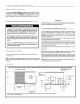
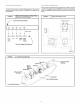
Thecondensatedrainoutletisa 314" (19.1mm)threadedfemalePVCconnectionlocated
at the bottom ofthe unitto the leftof the evaporatoraccesspanel.
Thecirculatingblowerandthe condenserfan createanegativepressureon the conden-
satedrain line that will preventthe condensatefromdrainingproperlywithouta trap. To
combatthis negativepressure,afield suppliedcondensatetrapthat willallow a standing
columnof waterofat least2" (50.8mm)MUSTbe installed.Theoutletofthe trap mustbeat
least 1"belowthe unitdrainconnection.Install the trapas nearto theunitas possible
for properdrainage.
A 3/4" (19.1mm)drainlineMUST be installedif requiredby localcodesor iflocationof unit
requiresit. Runthe drainlineto an open drainor othersuitabledisposalpoint.
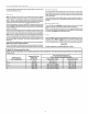
FIGURE 4
3/4" (19.1mm)
Threaded Female
PVC Fitting
Condensate Drain Information *
1"
(25.4mm)
3/4" (19.1mm)
Drain Line
33/4 ""
(82.5mm) 2" (50.8mm)
_,_kv * Condensate trap MUST be installed.
4. Electrical Wirinq
Electrical shock hazard.
Disconnect power at fuse box or service panel before making
any electrical connections.
Unit MUST be grounded to electrical service panel.
Failure to follow this warning can result in property damage,
personal injury, and/or death.
NOTE:All electricalwork MUST conformwith therequirementsof localcodesand ordi-
nancesand in the UnitedStates with NationalElectricalCodeANSI/NFPA70-1990 (or
current edition). Provide line voltagepowersupplyfrom a separatefused circuitwitha
disconnectswitch(whenrequired)locatedwithinsight ofthe unit.Supplyvoltage,amper-
age, fuseand disconnectswitchsizes MUST conformwithlocalcodes and ordinances.
Wiring MUSTbe protectedfrompossiblemechanicaldamageand MUST NOT interfere
with removalof access panels,filters, etc.
AllexposedlinevoltageconnectionsMUSTbemadethroughliquidtightconduitto prevent
waterfrom enteringthe unitthroughthe electricalaccess..
Ground Connections
A groundlugis installedonthe controlplate(orelectricheatmountingplate)forthe ground
connection.Use acopperconductorof the appropriatesize fromthe unitto a grounded
connectioninthe electricalservicepanelorto a properlydrivenand electricallygrounded
ground rod.
Line Voltage Wiring
DoNOTcompletelinevoltageconnectionsuntilunitispermanentlygrounded.All linevolt-
age connectionsand the groundconnection MUSTbe made withcopper wire.
Connectionsfor linevoltagearemadeon the unitelectricalcontrolplate(seeFIGURE7).
For access,removethe Blower/Electricalaccesspanel.
Refertoapplicablewiringdiagram andFIGURE6. Completetheline serviceconnections
to the contactor'L' terminalson the electricalcontrol plate.Check all screwterminalsto
ensuretheyare tight.
NOTE:Ifan ElectricHeatAccessoryisinstalled,refertotheElectricHeatAccessorysec-
tion of thismanualto determinelinevoltage connections.The ElectricHeat Accessory
mountsinsidethe unitin the heater box.Fieldsuppliedline voltage wiresfor theElectric
HeatAccessory(separatefromthe fieldsuppliedlinevoltagewirestothe unit)connectto
the appropriatecircuitbreaker (if used)in theElectric HeatAccessory.
Unit Disconnect
A DisconnectSwitchKitisavailablethat installsinsidetheunitora seperatecircuitbreaker
maybe installedtocontrolthe unit.Referto instructionsfollowingheaterinstallationsec*
tion.
Converting 230V Units to 208V
Toconvert230V unitsto 208V:
1.Turn electric power OFF.
2. Remove the blower/electrical access panel.
3. Locate the 24V control transformer.
4. Remove wire from the terminal labeled "240V" on the 24V control
transformer and reconnect it to the 208V terminal of the 24V control
transformer.
5. Replace the electrical/compressor access panel.
Low Voltage Wiring
For access,removethe electricalcontrol/bloweraccesspanel.
Refertothe connectionwiringdiagramforthe applicablemodelandto the instructionsin-
cludedwith thethermostat.
Route low voltagewiresthroughthe portlocatedon the rearpaneland upto the control
box.
NOTE:Ifan ElectricHeatAccessoryisinstalled,seethe ElectricHeatAccessoryInstalla-
tion Sectionof thismanualfor lowvoltage connections.