
Manual

ThermostatConnections
Thelocationofthethermostathasanimportanteffecton theoperationof the unit.Seethe
thermostatinstructionsfor properconnection. See FIGURE5 for Low VoltageWireHar-
ness Connections
Field Installed Equipment
Wiringto be doneinthefieldbetweenthe unitandother devices,or betweenseparatede-
viceswhicharefieldinstalledandlocated,MUSTNOTexceedthe temperaturelimitations
fortypeT wireand MUSTbe installedaccordingtothe manufacturer'sinstructionsforthe
devices.
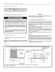
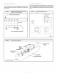
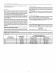
J Electronic Thermostat Low Voltage Wiring
FIGURE 5 Harness Connection Diagram
Typical Thermostat Subbase
[,q [?] [R,]
I I I I I
I I I I I
, = = , (when used)
I I I I I
i i , , [W'h
[Blue] [Green] [Red] [Yellow] ite]
Com Fan 24V Comp Elect.
(when Cool Heat
used) Acces.
Unit Low Voltage Wiring Harness.
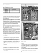
FIGURE 6 J Typical Connections at Unit
"F_'I
I
II
II
aCT I '
I I
I I
I
I
USE CO PPER CONDUCTORS ONLY
208/Z30V 60HZ 7PH
I
I
I
I
I
] • I
J
F _ 3 1
'1 K_ I I\ I
' -_ I I 'l'' I_
I BL I J GND L__ R__/_R
I
L=BL
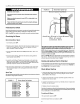
THERMOSTAT
OONNEOTION£
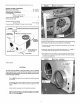
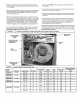
FIGURE 7 J Control Box Configuration
Blower
Relay or
Sequencer
Transformer
\
Anti-Cycle Time
(If Used)
Capacitor
Ground lug,
Contactor
Component Wire
Opening
Control Box
Line Volt Wire Entrance
Low Volt