
Manual

5. Electric Heat Installation
General Information
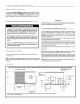
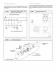
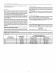
Adjusting Thermostat Anticipator
Set the heat anticipatorofthe thermostatto the propervalue.See instructionsprovided
with thethermostatbeforemakingthis adjustment.
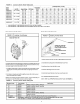
ModelNumber AnticipatorSettin_l
AMMK05AHBIA .18
AMM F,U/API_tA ,;Jb
.._IVl IVli% I U,_,I'ID/P_ .,.lt_
^_AHV4c^t _ntA ,_
A_A_I _OI'_AWRIA _A
Limit Controls
Thelimitcontrolsaremountedonthe faceofthe heaterandarewiredintothesupplywires
to eachelement. If thereis notenoughair flowthroughthe heater,the limitwill openand
breakthe powercircuit. The limitwill reset whenthe electricaccessorycoolsdown.
Time Delay Operation
TheheaterelementsareswitchedON andOFF throughoneormore controlswhichoper-
ate throughthe lowvoltagethermostatcircuit.
Thesecontrolsconsistof a numberoftimedelaysdependingon thespecificheatermodel.
An electricheataccessoryhas 1,2 or 3 of thesecontrols.Thefirsttimedelayisactivated
whenthethermostatcontactsclose.Approximately1to20secondslaterthe indoorblower
and the first heaterbankareenergized.Approximately70 secondsafter the first heater
bankis energizedthe remainingtime delaysand heaterbanks areenergized.
Staging
Some electric utilities require staging on electric heaters larger than 6 kilo-
watts. Therefore, the heater elements are turned on in 5 or 10 kW incre-
ments under control of the sequencers.
Ifstaging based on heat loss or demand is required, the use of accessory
outdoor thermostats is recommended. The heat sequencer wiring isde-
signed to be staged by breaking the 24V "Common" Leg (normally brown
or gray). Outdoor thermostats available through your wholesale supplier
allow the control of two or four stages of electrical heat.
Some indoor electronic thermostats may provide for multiple stages of
electric heat. When this type thermostat isused, it may be necessary to
break the 24V "Hot" leg of the sequencer (as fed from the "W' circuit at the
thermostat). This will require field modification of the control wiring and
should only be done by an experienced controls technician or electrician.
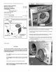
Install Heater
1. Shut OFF electric power at unit disconnect switch or service panel.
2. Remove the blower access panel from unit.
NOTE: Installation of field wiring and conduit for heaters to the
unit prior to installing the heater will simplify wiring of heaters.
3. From inside the blower compartment, remove the six screws on the
heater cover plate and save the screws. Discard the heater cover
plate.
The screws will be used later to mount the electric heat accessory
and its cover.
4. Remove the cardboard wrapper from the heater's elements.
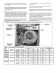
5. Insert the heater into the heater/blower box. Exercise caution to
prevent damage to heater elements.
6.Secure heater to heater/blower box with four of the six screws re-
moved in Step 3.
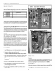
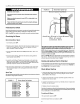
FIGURE 8 Typical Electric Heat Accessory
Breaker- Style Heater rl e
FIGURE 9 Installing The Electric Heat Accessory
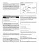
Heater Wiring
Grounding
Permanentlygroundthe electricheataccessoryin accordancewithlocalcodesandordi-
nancesandinthe UnitedStateswithNationalElectricalCodeANSIINFPA70-1990orcur-
rent edition. Use a copper conductor of the appropriate size from the electric heat
accessoryto the groundlug onthe circuitbreakerpanelas shownin FIGURE10.
Installing Wiring
Whenan electricheataccessoryis installed,two separatefieldpowersupplies MUSTbe
provided - one or more forthe electricheat accessoryand one for the unit.
1.Shut OFF electric power at unit disconnect or service panel.