
Manual
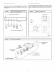

2.Installtheappropriatefieldsuppliedconduitfittingintotheheater
knockoutlocatedin the rear panel of the unit. The knockout is sized
11/4" in diameter.
NOTE: Check FIGURE 11 for heater/speed combinations that are
unacceptable.
3.Connect field installed copper ground wire(s) to the ground lug(s) on
the heater mounting plate. On models with more than one circuit, a
separate copper ground wire MUST be connected to a separate
ground lug for each circuit.
4. Route the field supplied line voltage wires for the heater to the line
side of the electric heat accessory's circuit breaker(s) or high voltage
wiring harness. Leave approximately 8" of excess wire so the break-
er or wiring harness may be moved to service. Make line voltage
connections to L3-L6 as appropriate. NOTE: If heaters without
breakers are used, route field wires to inside of unit and attach to
heater wires tagged L3-L6 as appropriate using supplied wire nuts.
5.Connect the black wire with terminal from the heater wire harness to
the loose black wire at the unit blower or appropriate speed tap if
lower speed is desired in electric heat mode.
FIGURE 10 1
6 Connect the red wire with terminal in the heater wire harness to the
loose red wire from the unit sequencer.
7.Connect the white wire from the heater wire harness to the white wire
from the thermostat at the field supplied low volt wire harness in the
control box.
8.Connect the grey and brown wires from the heater wire harness to
the blue wire from the unit 24V common. NOTE: If outdoor thermo-
stats are used for staging electric heat, connect the grey and brown
wires according to the thermostat instructions. See "Staging" in
Electrical Wiring Section of this Manual.
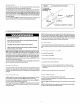
After completing installation of the heater, install the breaker rain shield on
the blower access panel according to the following instructions on page 8.
Ifusing a pigtail style heater, proceed to Start-Up Procedures for Auxiliary
Electric Strip Heat on page 10.
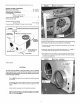
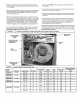
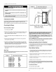
Typical Wiring Installation ( Breaker Style Heater Shown-Pigtail style also available)
Access hole for
low voltage
wires
Unit Line Volt-
age Wires
Knockout for unit
field supplied line
voltage wires
Ground
Lug
Heater
Ground Lug
Unit blower heat-
ing speed tap
leads
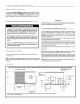
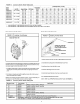
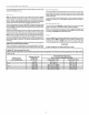
FIGURE 11 Accessory Electric Heater Electrical Data
MaximumOverourrent
HEATER Nominal Heating Supply Heater MininumCircuit ProtectiveDevice
MODEL UsedWith SupplyVoltage KW Rating BTUH CircuitNo. Amps Ampacity (Amps)
AMMK05AHA 2-5 TON 240-1-60 4.8 t6,382 L3_ L4 20.0 25.0 30
AMMK05AHB 208-1-60 3.6 t2,287 L3- L4 17.3 21.6 25
AMMK07AHA 2-5 TON 240-1-60 7.5 25,598 L3-L4 3t.2 39.1 45
AMMK07AHB 208-1-60 5.6 19,113 L3-L4 26.9 33.6 40
AMMK10AHA 2-5 TON 240-1-60 9.6 32,765 L3- L4 40.0 50.0 60
AMMK10AHB 208-1-60 7.2 24,574 L5- L6 34.6 43.3 50
L3- L4 40.0 50.0 60
AMMK15AHB 21/2-5 TON 240-1-60 14.4 49,t47 L5- L6 20.0 25.0 30
L3- L4 34.6 43.3 50
208-1-60 10.8 36,860 L5- L6 17.3 21.6 25
L3 - L4 40.0 50.0 60
AMMK20AHB 21/2-5 TON 240-1-60 19.2 65,530 L5 - L6 40.0 50.0 60
L3 - L4 34.6 43.3 50
208-1-60 14.4 49,t47 L5 - L6 34.6 43.3 50