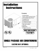
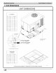
Installation Instructions Contents 1. Unit Dimensions 1. Safety Labeling ................... And Signal Words 2. Safe Installation the Unit 4. Electrical Wiring 6. Economizer 7. Start-up c@@ System 3 7 ............. 9 ........... 10 .............. 11 ....................... 13 ..................... Instructions .. 3 4 ................... Procedures 9. Maintenance 10. Rigging ..... .................. Accessory 8. Operation 80-30-04 Requirements 3. Locating 5.
I Installation Instructions Single Package Air Conditioners 1.
I Single Package Air Conditioners Installation Instructions 1. Safety Labeling And Signal Words DANGER, WARNING AND CAUTION CAUTION - Hazards or unsafe practices which COULD result in minor personal injury or product or property damThe signal words DANGER, WARNING and CAUTION are used to identify levels of hazard seriousness. The signal word DANGER is only used on product labels to signify an immediate hazard. The signal words WARNING and CAU- age.
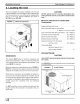
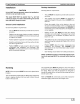
I Installation Instructions Single Package Air Conditioners I 3. Locating the Unit The unit is designed for outdoor installation may be installed on a concrete slab (or other form) at ground level, or on a rooftop with an form or a roof curb. Typical installations NO TAG through NO TAG. FIGURE 1 [ only. The unit adequate platadequate platare shown in CAUTION Do NOT operate unit in a corrosive atmosphere containing chlorine, fluorine, or any other corrosive chemicals.
I Single Package Air Conditioners Installation Rooftop CAUTION Unit will NOT operate properly unless it is installed level front to rear and side to side. The slope MUST NOT be greater than 1/8" per foot (10mm per meter). For side to side leveling, the control box side MUST always be lower. Ground Installation Level Installation Ground level platform requirements: The unit MUST be situated to provide safe access for servicing.
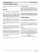
_ Installation Instructions Downflow Single Package Air Conditioners Conversion These units are shipped ready for horizontal operation but are adaptable to downflow use. To convert to downflow use, follow these steps: 1. Remove the blockoff plates found in the return air compartment and the supply air compartment (see FIGURE 3. NOTE: Blockoff plate in the supply air compartment only contains one screw. If reinstalling plate, back part of plate MUST fit into mating dimples on flange.
I Single Package Air Conditioners Installation Instructions 4. Electrical Wiring connections. If an economizer is installed, see the following section, Low Voltage Wiring With Economizer Option. Electrical shock hazard. Disconnect power at fuse box or service panel before making any electrical connections. Unit MUST be grounded to electrical service panel. Failure to follow this warning can result in property damage, personal injury, and/or death.
_ Installation Instructions tactor 'L' terminals on the unit electrical control plate. Check all screw terminals to ensure they are tight. Single Package Air Conditioners 5. Replace the electrical access panel. Field Installed NOTE: If an Electric Heat Accessory is installed, refer to the Electric Heat Accessory Installation Manual to determine line voltage connections. The Electric Heat Accessory mounts inside the unit.
I Single Package Air Conditioners 5. Air Distribution Installation Instructions System For airflow data (blower performance data, blower speed tap settings, filter sizes, etc.) see the Technical Support Manual. Ductwork NOTE: The total heat gain from the structure as expressed in total Btu/hr MUST be calculated by manufacturer's method or in accordance with "A.S.H.R.A.E. Guide" or "Manual J - Load Calculations" published by the Air Conditioning Contractors of America or in Canada "H. R.A.I.
_ Installation Instructions Single Package Air Conditioners I 6. Economizer Accessory The purpose of an economizer is to: • • Sequence Provide cool outdoor air to the conditioned space during the cooling cycle to minimize the use of compressors. Bring outdoor air into the conditioned space to meet minimum ventilation air requirements whenever the circulation blower is running.
I Single Package Air Conditioners Installation Instructions 7. Start-up Procedures cess panel and is also published in the Technical Support Manual. Wire the speed tap as required. Electrical shock hazard. Use extreme care during checks and procedures. Cooling all of the following Make sure electric power is turned instructed in appropriate steps. OFF as Failure to follow this warning can result in property damage, personal injury, and/or death.
Single Package Air Conditioners I _ Installation Instructions 4, Turn electric power ON. Nothing should start running. 5. Set thermostat fan switch to ON. The circulating air blower should come ON. , Resset thermostat fan switch to AUTO. The circulating air blower should go OFF. Nothing should be running.
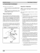
I Single Package Air Conditioners Installation Instructions c. Condenser fan motor - ON Cooling d. Circulating air blower - ON 1. Be sure that electric power is OFF 2, Set thermostat Heat-Cool 3. 4, Adjust thermostat ture. select to COOL. Turn electric power OFF, check the following: setting to below room tempera- Turn electric power ON for approximately one minute, then OFF. During power application check the following: a. Contactor - Contacts closing b. Compressor - ON FIGURE 7 5.
_ Installation Instructions Single Package Air Conditioners I 8. Operation Starting Unit After Shutdown Thermostat Cooling With the thermostat fan switch in the ON position, the circulating air blower will run continuously at the speed used for cooling. Adjust thermostat setting to desired temperature and set Heat-Cool selector switch to COOL. The unit will come on and operate automatically under control of the thermostat. Close all doors and windows.
I Single Package Air Conditioners Installation Instructions 9. Maintenance Monthly Checks Maintenance and Inspection be trimmed back so it is no closer than 30 inches (762mm) to unit. Condensate Drain Air Filters Check for condensate drainage. Clean as required. CAUTION Do NOT operate unit without air filters. Inspect filters at least monthly and replace or clean as required. Washable filters may be cleaned by soaking in mild detergent and rinsing with cold water.
_ Installation Instructions Single Package Air Conditioners Blower Motor Access 2, Remove the blower access panel. 3. Remove four screws securing blower housing to blower deck. If the unit has a support bracket, remove the two screws securing the support bracket to the blower housing. To access the blower motor follow the following steps. To remove the blower motor and/or the blower motor housing assembly, refer to Method 1 and Method 2 below. Slide entire housing toward you. 4, 1.
I Single Package Air Conditioners 10. Rigging FIGURE 11 Installation Instructions _ Rigging Instructions RIGGING INSTRUCTIONS ,&WARNING PROPERTY - DAMAGE, PERSONAL INJURY C AND/OR DEATH. All panels MUST be in place when rigging and lifting. Hook rigging shackles through holes in base rail, as shown in DetaiI-A. Use spreader bars, when rigging, to prevent unit damage. Be sure rigging and shackles are sufficient to handle weight listed below.
INTERNATIONAL COMFORT PRODUCTS LIMITED WARRANTY CERTIFICATE For Cooling SAVE THIS CERTIFICATE. province It gives you specific & Heating Products legal rights, and you may also have other rights which may vary from state to state and to province. If your unit needs servicing, contact a qualified dealer or qualified service technician of your choice. When requesting service, please have the model and serial number from each unit in your heating and/or cooling system readily available.
ADDITIONAL TERMS FOR RESIDENTIAL APPLICATIONS ONLY The Additional Terms for the components listed below are in addition to, and subject to, the General Terms on the reverse side of this page. Warranty coverage is limited to parts that fail due to defect in materials or workmanship during the specified term. CENTRAL GAS & OIL FURNACE HEAT EXCHANGERS* Gas Model Series: C9MPV. HgMPV. TgMPV. CgMPT. H9MPT. T9MPT. C9MPD. HgMPD. TgMPD: Limited Lifetime Warranty on heat exchangers.