
Installation guide


_ Installation Instructions Single Package Air Conditioners I
8. Operation
Starting Unit After Shutdown
Cooling
Adjust thermostat setting to desired temperature and set
Heat-Cool selector switch to COOL. The unit will come on
and operate automatically under control of the thermostat.
Close all doors and windows. The unit may run continuous-
ly for several hours or longer on the initial run because of
residual heat and moisture in the house. This is normal for
any air conditioning system.
CAUTION
Do NOT operate unit on cooling when the outdoor tem-
perature is below 40°F (4.4°C) unless an optional low
ambient kit is used. This is necessary to prevent pos-
sible damage to the compressor.
Heating
Ifthe unit has an Electric Heat Accessory installed, see the
Electric Heat Accessory Installation Instructions for start-
ing procedure.
Turning The Unit Off
1.
Set the thermostat selector switch to OFF and set the
thermostat fan switch to AUTO. To restart in cooling
mode, adjust the thermostat to the desired tempera-
ture and set the thermostat Heat-Cool selector
switch to COOL. To restart in heating mode if Electric
Heat Accessory is installed, adjust the thermostat to
the desired temperature and set the thermostat
Heat-Cool selector switch to HEAT.
2. To shut the unit down completely, turn electric power
OFF.
Thermostat Fan Switch Operation
With the thermostat fan switch inthe ON position, the circu-
lating air blower will run continuously at the speed used for
cooling.
With the thermostat fan switch in the AUTO position, the
circulating air blower will only run during each cooling cycle
(or heating cycle if Electric Heat Accessory is installed).
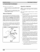
Adjusting Room Temperatures
Ifthe temperature in individual rooms is not as desired, bal-
ance the system by adjusting the dampers in the branch
ducts. Adjust a little at a time and wait a day after each
change to judge the effect. Once the dampers are adjusted
for normal weather conditions, it is best to leave them that
way. Compensate for temporary weather changes by ad-
justing the thermostat setting.
FIGURE 8 Typical Branch Duct Dampers
b2J