
Installation guide


I Single Package Air Conditioners Installation Instructions
4. Electrical Wiring
Electrical shock hazard.
Disconnect power at fuse box or service panel
before making any electrical connections.
Unit MUST be grounded to electrical service pan-
el.
Failure to follow this warning can result in prop-
erty damage, personal injury, and/or death.
NOTE: All electrical work MUST conform with the require-
ments of local codes and ordinances and in the United
States with National Electrical Code ANSI/NFPA 70-1990
(or current edition) and in Canada with CSA C22.1 - Cana-
dian Electrical Code Part 1 (or current edition). Provide line
voltage power supply from a separate fused circuit with a
disconnect switch (when required) located within sight of
the unit. Supply voltage, amperage, wire, fuse and discon-
nect switch sizes MUST conform with specifications in the
Technical Support Manual and on the unit rating plate.
Wiring MUST be protected from possible mechanical dam-
age and MUST NOT interfere with removal of access pan-
els, filters, etc.
All exposed wiring and connections MUST be made with
weatherproof cable or wire unless installed in conduit.
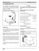
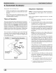
Low Voltage Wiring
Low voltage connections are made on the low voltage ter-
minal board inside the electrical compartment (see
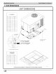
FIGURE 5). For access, remove the electrical access pan-
el (see FIGURE 2).
Refer to the Technical Support Manual for the connection
wiring diagram for the applicable model and to the instruc-
tions included with the thermostat.
Route low voltage wires through the port located at the bot-
tom left corner of the blower access panel side of the unit.
Route low voltage wires behind unit cornerpost, through
the wire clip provided, and up to the low voltage terminal
board.
NOTE: If an Electric Heat Accessory is installed, see the
Electric Heat Accessory Installation Manual for low voltage
connections. If an economizer is installed, see the follow-
ing section, Low Voltage Wiring With Economizer Option.
Low Voltage Wiring With Economizer
Option
Same as the above Low Voltage Wiring section except re-
fer to the connection wiring diagram supplied with the
economizer. Also, a pre-wired plug for the economizer is
located just inside the return air opening.
Thermostat
The location of the thermostat has an important effect on
the operation of the unit. FOLLOW THE INSTRUCTIONS
INCLUDED WITH THE THERMOSTAT FOR CORRECT
LOCATION, MOUNTING AND WIRING.
Unit Without Economizer
A field supplied single stage thermostat is required.
Unit With Economizer
A field supplied two stage thermostat is recommended for
use with an economizer. If a single stage thermostat is
used, the compressor will not start if the economizer can
not satisfy the demand for cooling.
Ground Connections
A ground lug is installed on the electrical control plate for
the ground connection (see FIGURE 5). Use a copper con-
ductor of the appropriate size from the unit to a grounded
connection in the electrical service panel or to a properly
driven and electrically grounded ground rod. See WARN-
ING above.
Line Voltage Wiring
Do NOT complete line voltage connections until unit is per-
manently grounded. All line voltage connections and the
ground connection MUST be made with copper wire.
Connections for line voltage are made on the unit electrical
control plate (see FIGURE 5). For access, remove the
electrical access panel (see FIGURE 2).
Refer to applicable wiringdiagram in the TechnicalSupport
Manual. Complete the line service connections to the con-
171