
Installation guide


_ Installation Instructions Single Package Air Conditioners I
tactor 'L' terminals on the unit electrical control plate.
Check all screw terminals to ensure they are tight.
NOTE: If an Electric Heat Accessory is installed, refer to
the Electric Heat Accessory Installation Manual to deter-
mine line voltage connections. The Electric Heat Accesso-
ry mounts inside the unit. Field supplied line voltage wires
for the Electric Heat Accessory (separate from the field
supplied line voltage wires to the unit) connect to the circuit
breaker(s) in the Electric Heat Accessory.
Converting 230V Units to 208V
To convert 230V units to 208V:
1. Turn electric power OFF.
5. Replace the electrical access panel.
Field Installed Equipment
Wiring to be done in the field between the unit and other de-
vices, or between separate devices which are field
installed and located, MUST NOT exceed the temperature
limitations for type T wire and MUST be installed according
to the manufacturer's instructions for the devices.
Final Electrical Check
Make a final wiring check to be sure system is correctly
wired. Inspect field installed wiring and the routing to en-
sure that rubbing or chafing due to vibration will not occur.
2. Remove the electrical access panel.
3. Locate the 24V control transformer.
NOTE: Wiring MUST be installed so it is protected from
possible mechanical damage.
4. Remove wires from the terminal labeled "240V" on
the 24V control transformer and reconnect them to
the 208V terminal of the 24V control transformer.
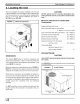
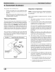
FIGURE 5 I Typical Wiring Installation
Electrical Control
Plate
Low Voltage Ter-
minal Board
Contactor 'L' Ter-
minals
Ground lug
Carefully route low
voltage wires behind
unit cornerpost
through wire clip
Field supplied line
voltage wires
Knockout for Elec-
tric Heat Accessory
field supplied line
voltage wires
8L2J