
Installation guide


THERMOSTAT HEAT ANTICIPATOR
Some thermostats have an adjustable heat anticipator. The
heat anticipator prevents temperature overshoot in heating
mode. If the heat doesn't turn off until the set point
temperature on the thermostat is exceeded, then the
anticipator setting is too low. If the heat turns off before the
thermostat reaches the set point temperature on the
thermostat, then the anticipator setting is too high. Follow
the thermostat instruction manual for proper adjustment of
the heat anticipator.
Final Electrical Check
1. Make a final wiring check to be sure system is correctly
wired. Inspect field installed wiring and the routing to
ensure that rubbing or chafing due to vibration will not
occur.
NOTE: Wiring MUST be installed so it is protected from
possible mechanical damage.
5. DUCTWORK
Ductwork Sizing
The maximum recommended velocity in trunk ducts is 1000
feet per minute. The maximum recommended velocity in
branch ducts is 800 feet per minute.
barrier installed around it. The insulation and vapor barrier
must be protected against potential damage. Caulking,
flashing, and other means of providing a permanent
weather seal must be used.
Ductwork Connections
The use of flexible, non-combustible connectors between
main trunk ducts and supply and return air plenums is
permitted. If flexible connectors are used, they should be
protected from potential mechanical damage such as
punctures and tears.
NOTE: When connecting the supply and return plenums to
the unit, make sure that the plenums are sealed against the
side casing of the unit and do not interfere with removal of
the top of the unit.
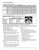
FILTERS
All return air MUST pass through a filter before entering the
unit. An electronic air cleaner, optional filter racks, or other
accessible filter arrangement must be installed in the return
air ductwork. Minimum recommended filter sizes are listed
in FIGURE 5 and are based on maximum face velocities of
300 ft/min for disposable filters and 500 ft/min for washable
(high velocity) filters. See FIGURE 5 for filter sizes.
Ductwork sizing affects the discharge temperature, airflow
velocity, and efficiency of the system. Be sure to properly
size ductwork to the capacity of the unit and to the airflow
requirements of the conditioned space. Failure to properly
size ductwork can result in inadequate airflow and poor
efficiency. Undersized ductwork may result in tripped limit
controls and premature failure of compressors, motors and
other components.
REDUCED EQUIPMENT LIFE HAZARD
Failure to follow this caution may result in improper
unit operation.
Do not operate the unit without a filter,
Ductwork Insulation
Ductwork installed outdoors must have a minimum 2" thick
fiberglass "wrap" insulation and a weatherproof vapor
FIGURE 5 Filter Sizes
PAF3 Filter sizes
Disposable Filters
Model
PAF324000K00A1
PAF330000K00A1
PAF336000K00A1
PAF342000K00A1
PAF348000K00A1
PAF354000K00A1
Nominal Size
(Qty x w x d)
1 x 20" x 20"
1 x 20" x 24"
2x 15"x20"
2x 18"x20"
2 x20"x20"
2 x20"x24"
Minimum Area
(sq inches)
384
480
576
672
768
900
Nominal Size
(Qty x w x d)
1 x 12" x 20"
1 x 15" x 20"
1 x 18" x 20"
1 x 20" x 20"
1 x 20" x 24"
1 x 24" x 24"
Wasable Filters
Minimum Area
(sq inches)
231
288
346
4O4
461
54O