
Installation guide


6. AIRFLOW ADJUSTMENT
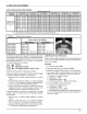
CIRCULATING AIR BLOWER SPEEDS
BLOWERPERFORMANCEDATA
ModeINumber PAF324000KOOA1 PAF330000K00A1 PAF336000K00AI PAF342000K00AI PAF348000K00AI PAF354000KOOA1
SpeedTap 1 2 3 4 1 2 3 4 1 2 3 4 t 2 3 4 t 2 3 4 t 2 3 4
0.1 891 1136 986 1076 1286 1352 1162 1278 1529 1652 1138 1240 1505 1643 1154 1245 1750 1908 1348 1449 1998 2173
0.2 845 1098 949 1038 1225 1311 1118 1233 1484 1607 1087 1189 1467 1609 1084 1170 1696 1864 1274 1372 1943 2113
0.3 804 1056 908 997 1186 1274 1062 1191 1440 1574 1041 1145 1431 1577 1005 1110 1643 1819 1218 1318 1895 2067
AirDeliveryinCFM 0.4 758 1020 856 973 1158 1233 1014 1149 1402 1541 989 1104 1398 1541 940 1034 1592 1770 1151 1258 1850 2032
@Varying External 0.5 707 980 8t9 913 1129 1203 958 1108 1364 1501 940 1063 1363 1509 880 972 1547 1720 1085 1195 1800 2003
Static Pressure (in. 0.6 649 920 781 875 1085 1162 892 1060 1326 1462 865 1010 1324 1476 832 924 1497 1678 1032 1130 1750 1962
w.c.) 0.7 582 785 717 840 1044 1119 826 1005 1284 1426 806 952 1283 1439 780 875 1443 1632 989 1086 1705 1904
0.8 509 569 664 786 1004 1066 780 943 1238 1384 752 891 1234 1402 713 836 1400 1586 954 1048 1659 1822
0.9 318 612 717 948 989 735 892 1179 1338 694 828 1175 1352 663 773 1354 1538 904 1000 1602 1727
1 554 659 755 774 675 844 1123 1277 646 773 1120 1264 613 720 1302 1494 85I 946 1530 1603
Notes:
FIGURE 6
Air Defivery @ listed external static pressre are taken at 230Volts with Dry coil, no filter and approved heater
For wet coit add .05in. wc to Static Pressure measurement Note for 208 Volts applications, reduceairflow by 15%
Blower Tap Connections
Blower Speed Tap Settings
Rated Airflow High Airflow
PAF324000K Speed Tap 1 Speed Tap 3
PAF330000K Speed Tap 2 Speed Tap 3
PAF336000K Speed Tap 2 Speed Tap 3
PAF342000K Speed Tap 3 Speed Tap 4
PAF348000K Speed Tap 3 (Hi); 2 (Lo) Speed Tap 4 (Hi); 3 (Lo)
PAF354000K Speed Tap 3 (Hi); 2 (Lo) Speed Tap 4 (Hi); 3 (Lo)
Verify that the proper blower speeds for heating and cooling
are selected on the blower motor by removing the blower
access panel and inspecting the blower motor, The motor
has 4 speeds numbered "1", "2", "3", and "4", The wires for
the speed selection are as follows:
Red _ Heating
Black _ High Stage Cooling
Violet _ Low Stage Cooling (4 & 5 ton only)
Using the same speed for Heating and Cooling.
If the same speed is required for heating and high stage
cooling the following procedure must be used:
1. Set Red wire on proper speed selection on blower
motor.
2. Remove Black wire from "COOL" (2 - 3.5 Ton models)
or "HI" (4 - 5 Ton Models) on Blower Interface Board.
Tape end of Black lead using electrical tape.
3. Jumper the Red wire to both the "Heat" terminal and
either the "COOL" (2 - 3.5 Ton models) or'HI" (4 - 5Ton
Models) terminal on the Blower Interface Board.
If the same speed is required for heating and low stage
cooling (4 & 5 Ton models only), the following procedure
must be used:
1. Set Red wire on proper speed selection on blower
motor.
2. Remove Violet wire from "LO" on Blower Interface
Board. Tape end of Violet lead using electrical tape.
3. Jumper the Red wire to both the "Heat" terminal and the
"LO" terminal on the Blower Interface Board.
CONTINUOUS FAN OPERATION
Continuous fan speed operates at the cooling speed for 2
th ru 3-1/2 ton models and at the low stage cooling speed for
4 and 5 ton models.
COOLING
1. Turn electric power OFF
2. Set thermostat Heat-Cool select to COOL.
3. Adjust thermostat setting to below room temperature.
4. Turn power ON, for approximately one minute, then
OFF. During power application check the following:
a. Contactor - Contacts Closing
b. Compressor - ON
c. Condenser fan motor - ON
d. Circulating Air Blower - ON 0 second delay
5. Turn power OFE check the following:
a. Contactor contacts opening.
b. Compressor - OFF
c. Condenser fan motor - OFF
d. Circulating blower - OFF after a 60 second delay for
2 thru 3-1/2 ton models and a 90 second delay for 4
and 5 ton models.
171