
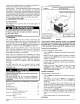
Installation guide


NOTE: All access panels MUST be secured in place before
hoisting.
The unit should be hoisted with two lifting slings. Attach the
slings to rigging shackles that have been hooked through
holes in the base rail,
Two spreader bars MUST be placed on top of the unit to
protect the unit from damage from the pressure exerted by
the slings. Make sure that all equipment is adequate to
handle the weight ofthe unit and that the slings will not allow
the unit to shift,
Refer to Figure 20 on the back cover of this manual for
illustrated rigging instructions and weight chart,
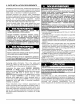
DOWNFLOW CONVERSION
NOTE: In downflow applications with roof curbs or jack
stands, the center rail under the unit must be removed. The
center rail is attached to the base rail with screws.
These units are adaptable to downflow use, To convert to
downflow use, follow these steps:
1, Remove the blockoff plates found in the return air
compartment and the supply air compartment.
NOTE: Blockoff plate in the supply air compartment only
contains one screw. If reinstalling plate, back part of plate
MUST fit into mating dimples on flange. To reinstall, slant
plate into dimples, then put plate into position and fasten
with screw,
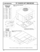
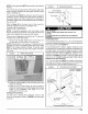
I FIGURE 2 I Heating vent Assembly I
Screws for
"B" Chassis
(473/8 x 473/8)
/
FIGURE 3 1 Heating Vent Assembly
Flue Support
(Shipped mounted to unit
Flue Cover
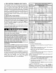
Condensate Drain
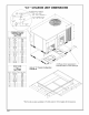
The condensate drain outlet is a 3/4" (19.1mm) female PVC
connection located atthe bottom ofthe unit to the right of the
filter access panel (see FIGURE 4).
The circulating blower creates a negative pressure on the
condensate drain line that can prevent the condensate from
draining properly. To combat this negative pressure, a field
supplied condensate trap that will allow a standing column
of water of at least 2" (50.8mm) MUST be installed. Top of
outlet from trap MUST be at least 1" (25.4mm) below top of
outlet from unit. Install the trap as near to the unit as
possible for proper drainage,
A 3/4" (19.1 mm) drain line MUST be installed if required by
local codes or if location of unit requires it. Run the drain line
to an open drain or other suitable disposal point,
/ Condensate Drain Information*
FIGURE 4
25-1/2 ("B" Chassis)
32-1/4 ("C" Chassis)
2. Install the removed plates on the horizontal return and
supply air openings.
3, Install roof curb on the building. Be sure to follow all
directions included with curb and all applicable building
codes in your installation. See page 2 or 3 for
appropriate roof curb to use.
Heating Vent Assembly
The flue cover is packed with installation screws in the
return air compartment, Refer to FIGURE 3 and assemble
as shown,
3/4" (19.1mm)
Threaded Female
(25.4mm)
2" (50.8mm)
* Condensate trap MUST be installed.
171