
Manual

1. Safety Labelinq and Siqnal Words
Danger, Warning and Caution
The signal words DANGER, WARNING and CAUTION are used to identi-
fy levels of hazard seriousness. The signal word DANGER is only used on
product labels to signify an immediate hazard. The signal words WARN-
ING and CAUTION will be used on product labels and throughout this
manual and other manuals that may apply to the product.
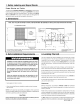
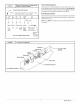
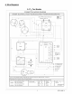
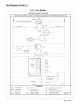
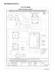
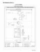
2. Dimensions
NOTE: DUCT COLLARS ATTACHED TO SUPPLY AND RETURN MUST BE REVERSED AT INSTALLATION. SEE INSTRUCTIONS ON PAGE 2.
ALL DIMENSIONS IN INCHES
27
PRESSURE
<i PORTS
COIL
ACCESS
PANEL
" tl_ I
26 3/4
81 \
CONDENSATE DRAIN
CONNECTION
ROUND FLANGE
WILL 3/8 DIA HOLE**
ACCOMMODATE
14" DIA.
RETURN DUCT
m___
. 1 1/4 DIA.*
/ 1 1/4 DIA.*
10 9
3 11/2 I-1 1/2
41 1/2
* ELECTRICAL ACCESS FOR LINE VOLTAGE POWER SUPPLY-ONE FOR UNIT, ONE FOR HEATER
** FOR LOW VOLTAGE WIRING
ROUND SHAPED FLANGE WILL
ACCOMMODATE 12" DiA
SUPPLY DUCT
3. Safe Installation Requirements 4. Locating The Unit
Installation or repairs made by unqualified persons can result
in hazards to you and others. Installation MUST conform with
local building codes or, in the absence of local codes, with the
National Electrical Code NFPA70-1990 or current edition.
The information contained in this manual is intended for use
by a qualified service technician familiar with safety proce-
dures and equipped with the proper tools and test instru-
ments.
Failure to carefully read and follow all instructions in this
manual can result in unit malfunction, property damage, per-
sonal injury and/or death.
• Seal supply and return air ducts.
• Check to see that filters are installed correctly and are the proper
type and size.
NOTE: It is the personal responsibility and obligation of the customer to
contact a qualified installer to ensure that the installation is adequate and
conforms to governing codes and ordinances.
CAUTION
Do NOT operate unit in a corrosive atmosphere containing chlorine,
fluorine, or any other corrosive chemicals.
The unit is designed for outdoor installation only. Place the unit on a plat-
form at ground level. The unit may be installed on a concrete slab of 48"
(1219mm) x 48" (1219mm) dimensions. Cement blocks on a 3" sand
footing will also work. The slab or blocks SHOULD NOT be in contact with
any part ofthe structure. Check local codes covering zoning, noise, plat-
forms, etc..
If practical avoid locating next to fresh air intakes, vent or bedroom win-
dows. Noise may carry into the openings and disturb people inside.
Avoid installations under roof overhangs without guttering. Water draining
from the roof onto the unit could produce excessive noise, and may cause
ice to build up on coil or fan.
Placement of the unit should be in a well drained area or the unit MUST be
supported high enough so runoff will not enter the unit.
Do not locate unit where heat, lint or exhaust fumes will be discharged on
unit (as from dryer vents.)
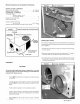
Clearances
Minimum clearances, as specified in FIGURE 1, MUST be maintained
from adjacent structures to provide adequate air circulation and room for
service personnel.
While minimum clearances are acceptable for safety reasons, they may
not allow adequate air circulation around the unit for proper operation.
Whenever possible, it is desirable to allowadditional clearance, especially
around the condenser inlet and discharge openings.
Do NOT install the unit in a recessed or confined area that will permit dis-
charged air from the condenser to recirculate to the condenser inlet.
2 427 01 1004 01