
Manual
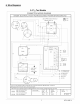
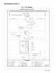
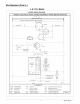

Minimum Clearances to Combustible Construction
SERVICE ACCESS CLEARANCES
Blower Access Panel Side .......................... 30" (762mm)
Electrical Access Panel Side ........................ 30" (762mm)
OPERATIONAL CLEARANCES
Combustible Base
(Wood or Class A, B or C
roof covering material) ......................... 0"
Supply and Return Air Ducts ................................. 0"
Duct Connection Side
............................................. 0 !_
Clearance between Overhang
and Top of Unit ..................... 48" (1219mm)
Clearance around Condenser Coil area to wall or shrubs ........ 10"
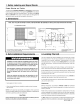
FIGURE i Minimum Clearances and Access Panels
Overhang
Evaporator 48" Minimum Overhang Clearance
Access Panel
J
10"around
f condenser
coil area
Blower/Electrical
Access Panel
,,_ Cover Plate
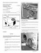
Installation
CAUTION
The unit must be installed with a slope no greater than 1/8" per foot
(10mm per meter), For side to side leveling, the condensate drain
side side MUST always be lower.
The unit MUST be situated in such a way as to provide safe access
for servicing.
The platform may be made of either concrete or pressure treated
wood and MUST be level and strong enough to support the unit's
weight.
Position platform separate from the building's foundation.
Install in a well-drained area, with the top surface of the platform
above grade level and above the average winter snow levels to
prevent coil blockage.
Platform MUST be high enough to allow for proper condensate
drainage.
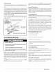
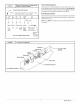
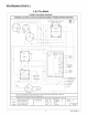
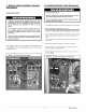
Installing Duct Collars
Duct collars are supplied with the unit and are attached to the supply and
return openings with the flanges to the inside and must be reversed before
unit's installation.
1.Remove the screws from the collars and reverse them so the flange
is to the outside.
2.Make sure when pushing the collars into place that the "V" flange of
the collars seats into the supply and return holes securely.
3.Re-install screw in each collar so it goes through both of the holes in
the collar end. It does not matter how the ends of the collar overlap
in order to accomplish this.
FIGURE ;3 I Duct Collar Installation
3 427 01 1004 01