
Manual
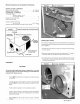

Condensate Drain
The condensate drain outlet is a 3/4" (19.1 mm) threaded female PVC con-
nection located at the bottom of the unit to the left of the evaporator access
panel.
The circulating blower and the condenser fan create a negative pressure
on the condensate drain line that will prevent the condensate from drain-
ing properly without a trap. To combat this negative pressure, a field sup-
plied condensate trap that will allow a standing column of water of at least
2" (50.8mm) MUST be installed. The outlet of the trap must be at least 1"
below the unit drain connection. Install the trap as near to the unit as
possible for proper drainage.
A 3/4" (19.1 mm) drain line MUST be installed if required by local codes or if
location of unit requires it. Run the drain line to an open drain or other suit-
able disposal point.
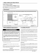
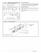
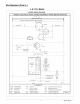
FIGURE 4 J Condensate Drain information*
i
3/4" (19,1mm)
Threaded Female
PVC Fitting
1,, I
(25.4mm)
3/4" (19.1mm)
Drain Line
* Condensate trap MUST be installed.
5. Unit Electrical Wiring
Electrical shock hazard.
Disconnect power at fuse box or service panel before making
any electrical connections.
Unit MUST be grounded to electrical service panel.
Failure to follow this warning can result in property damage,
personal injury, and/or death.
NOTE: All electrical work MUST conform with the requirements of local
codes and ordinances and in the United States with National Electrical
CodeANSI/NFPA 70-1990 (or current edition). Providelinevoltage pow-
er supply from a separate fused circuit with a disconnect switch (when re-
quired) located within sight of the unit. Supply voltage, amperage, fuse
and disconnect switch sizes MUST conform with local codes and ordi-
nances.
Wiring MUST be protected from possible mechanical damage and MUST
NOT interfere with removal of access panels, filters, etc.
All exposed line voltage connections MUST be made through liquid tight
conduit to prevent water from entering the unit through the electrical ac-
cess..
Ground Connections
A ground lug is installed on the control plate (or electric heat mounting
plate) for the ground connection. Use a copper conductor of the appropri-
ate size from the unit to a grounded connection in the electrical service
panel or to a properly driven and electrically grounded ground rod. See
warning on this page.
Line Voltage Wiring
Do NOT complete line voltage connections until unit is permanently
grounded. All line voltage connections and the ground connection MUST
be made with copper wire.
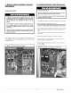
Connections for line voltage are made on the unit electrical control plate
(see FIGURE 6). For access, remove the Blower/Electrical access panel.
Refer to applicable wiring diagram in this Manual. Complete the line ser-
vice connections to the contactor 'U terminals on the electrical control
plate. Check all screw terminals to ensure they are tight.
NOTE: If an Electric Heat Accessory is installed, refer to the Electric Heat
Accessory section of this manual to determine line voltage connections.
The Electric HeatAccessory mounts inside the unit in the heater box. Field
supplied line voltage wires for the Electric Heat Accessory (separate from
the field supplied line voltage wires to the unit) connect to the appropriate
circuit breaker (if used) in the Electric Heat Accessory.
Converting 230V Units to 208V
To convert 230V units to 208V:
1.Turn electric power OFF.
2.Remove the blower/electrical access panel.
3. Locate the 24V control transformer.
4. Remove wire from the terminal labeled "240V" on the 24V control
transformer and reconnect it to the 208V terminal of the 24V control
transformer.
5. Replace the electrical/compressor access panel.
Low Voltage Wiring
For access, remove the electrical control/blower access panel.
Referto the connectionwiringdiagramfor the applicablemodeland to the
instructions included with the thermostat.
Route low voltage wires through the port located on the rear panel and up
to the control box.
NOTE: If an Electric Heat Accessory is installed, see the Electric Heat Ac-
cessory Installation Section of this manual for low voltage connections.
Thermostat Connections
The location of the thermostat has an important effect on the operation of
the unit. See the thermostat instructions for proper connection. See
FIGURE 5 for Low Voltage Wire Harness Connections
4 427 01 1004 01