
Manual
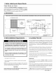
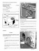
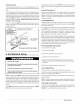
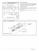
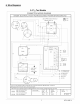
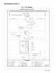
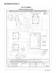
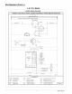
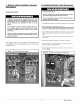

FIGURE5 I HarnessElectr°niCconnectionTherm°statDiagramL°WVoltage Wi ri ng
_NOT Typical Thermostat SubbaseES: 1 Common maybe "B" or "X" on some T-stats.
2 "W" may be "W2" on some T-stats.
[?] [,R] [O]
I I I I
I I I I
i (wher],used)
W2
[c]1
I
i
I I I I
I I I I /
A A A A
A
I I I I I
[Blue] [Green] [F_ed] [Yellow] [W_hite]
Corn Fan 24V Comp Elect.
(when Cool Heat
used) Acces.
Unit Low Voltage Wiring Harness.
',, [Orange] "_,Xk
When outdoor \
thermostat is \
used, route this. I
i
Reversing
valve
(energized
in cooling)
Field Installed Equipment
Wiring to be done in the field between the unit and other devices, or be-
tween separate devices which are field installed and located, MUST NOT
exceed the temperature limitations for type T wire and MUST be installed
according to the manufacturer's instructions for the devices.
Final Electrical Check
Make a final wiring check to be sure system is correctly wired. Inspect field
installed wiring and the routing to ensure that rubbing or chafing due to
vibration will not occur.
NOTE: Wiring MUST be installed so it is protected from possible mechani-
cal damage.
FIGURE 6 I Control Box Configuration
Capacitor_
Ground lug%__ _oJ Component Wire
Contaotor Opening
Blower J___ _ //
Sequencer __;_ /_
Transformer\ ____. F //
oooooox
,neVo,We n,anoe
Low Volt Wire Entrance
5 427 01 1004 01