2-inch Network Speed Dome Installation Manual Version 1.0.
Table of Contents 1 INTELLIGENT SPEED DOME INSTALLATION .................................................. 1 1.1 Installation Environments ..................................................................................................................... 1 1.2 Check installation space and installation location intension ........................................................... 1 1.3 Please keep all package material well for future use ..............................................................
5 APPENDIX Ⅱ12V DC WIRE GAUGE AND TRANSMISSION DISTANCE RELATIONSHIP SHEET ............................................................................................ 7 6 APPENDIX Ⅲ WIRE GAUGE REFERENCE SHEET ..........................................
Welcome Thank you for purchasing our speed dome! Please read the following safeguards and warnings carefully before you install or use the product! iii
Important Safeguards and Warnings Safety Measures 1. Qualified Engineer Needed The installation engineer or maintenance engineer shall have corresponding CCTV system installation certificate or maintenance qualification certificate. The installation engineer or maintenance engineer shall have qualification certificate for work at height.
electromagnetic field. 7. Violent vibration or crash is not allowed during transportation and application. 8. Before you connect the cable, install or uninstall, or begin the daily maintenance work, please turn off the power and unplug the power cable. 9. Please make sure the produce is secure firmly on the wall or the ceiling. 10. Please turn off the power and unplug the power cable, If there is any smoke, disgusting smell, or noise. Please contact your local retailer or customer service centre for help.
This series product shall be away from the strong electromagnetism radiant, please keep it away from wireless power, TV transmitter, transformer and etc. 7. Daily Maintenance Please use the soft cloth to clean dust on the shell, or you can use soft cloth with cleaning liquid to clean the shell and then use soft cloth to make it dry. Do not use gasoline, dope thinner or other chemical material to clean the shell. It may result in shell transfiguration or paint flake.
1 INTELLIGENT SPEED DOME INSTALLATION 1.1 Installation Environments Basic Requirement All installation and operation here should conform to your local electrical safety codes. Before installation, please open the package and check all the components are included. Please make sure the speed dome installation environment and installation mode can meet your requirement. If there is special requirement, please contact your local retailer for more information.
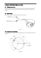
2 SETUP BEFORE INSTALLATION 2.1 Check Accessories Before the installation, please check the accessories one by one according to the packing list. Please make sure all the components listed are included. (Please check the container list for details.) 2.2 Open Device Remove the package and then take out the device. See Figure 2-1. Figure 2-1 2.3 Installation Position Map The installation position map is used for drilling positioning on the ceiling and outlet position. See Figure 2-2.
2.4 SD Card Slot and Rest Button SD card slot and button is shown in Figure 2-3. Please make sure the SD card is in the non read-write state when removing it. Otherwise, it may result in data loss and SD card damage. The button is used for default setting. Long press Reset button for more than 5 seconds, the system configuration information will be recovered to default setting.
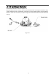
3 CAMERA INSTALLATION 2-inch network speed dome mainly adopts ceiling mount mode, which can be installed on the ceiling or wall. 3.1 Component Installation The installation of pedestal seal ring is shown in Figure 3-1. Figure 3-1 The ceiling mount speed dome is shown in Figure 3-2.
3.2 Installation Steps 3.2.1 Installation Environments The ceiling mount speed dome can be installed in the hard construction ceiling in the indoor environment. Before the installation, please make sure: The ceiling is thick enough to install the expansion bolt. The ceiling can at least sustain the 8x weight of the speed dome. 3.2.2 Installation Steps Note: There are two outlet modes for ceiling mount installation. Don’t drill hole on the ceiling, and open wire outlet from the side of the speed dome.
4 APPENDIX Ⅰ LIGHTENING PROTECTION AND SURGE PROTECTION This series speed dome adopts TVS lighting protection technology. It can effectively prevent damages from various pulse signals below 2000W, such as sudden lighting and surge. While maintaining your local electrical safety code, you still need to take necessary precaution measures when installing the speed dome in the outdoor environment.
5 APPENDIX Ⅱ12V DC WIRE GAUGE AND TRANSMISSION DISTANCE RELATIONSHIP SHEET The recommended max transmission distance is under the following environments: The wire diameter is fixed and the DC 12V power voltage loss rate is below 10%. For the device of DC power supplying, the max allowed voltage loss rate is 10%. All the wires listed in the following sheet are copper wire. (Copper wire resistance mm Feet(m) 0.8000 ) 1.000 1.250 2.000 w 5 122.13 (37.23) 190.83(58.16) 298.17(90.88) 10 61.06(18.
6 APPENDIX Ⅲ WIRE GAUGE REFERENCE SHEET Metric bare wire diameter (mm) 0.050 0.060 0.070 0.080 0.090 0.100 0.110 0.130 0.140 0.160 0.180 0.200 0.230 0.250 0.290 0.330 0.350 0.400 0.450 0.560 0.600 0.710 0.750 0.800 0.900 1.000 1.250 1.500 2.000 2.500 3.000 AWG SWG 43 42 41 40 39 38 37 36 35 34 33 32 31 30 29 28 27 26 25 24 23 22 21 20 19 18 16 15 12 / / 47 46 45 44 43 42 41 39 / 37 / 35 / 33 31 30 29 28 / 24 23 22 / 21 20 19 18 / 14 / / 8 Bare wire cross section (mm2) 0.00196 0.00283 0.00385 0.
Note • This manual is for reference only. Slight difference may be found in the user interface. • All the designs and software here are subject to change without prior written notice. • All trademarks and registered trademarks are the properties of their respective owners. • If there is any uncertainty or controversy, please refer to the final explanation of us. • Please visit our website or contact your local service engineer for more information.