ICU Eve Mini TM MANUAL / HANDBOEK / ANLEITUNG / MANUEL / MANUALE
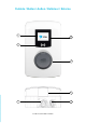
Outside / Buiten / Außen / Extérieur / Esterno 1 2 3 4 5 6 7 H x W x D: 370 x 240 x 130 mm
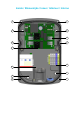
Inside / Binnenzijde / Innen / Intérieur / Interno 8 8 9 9 10 8 8 11 12 13 9 9 8 8
Package Contents / Inhoud Verpakking / Inhalt Verpackung / Contenu de l‘emballage / Contenuto della confezione ICU Eve Mini 1x 1x 1x 1x 4x 4x 4x 4x 1x (fixed cable version) Pole / Paal / Säule / Pôle / Polo 1x 2x Types / Varianten / Varianten / Variantes / Varianti RFID / Display Plug & Charge 1x
Contact / Contact / Kontakt / Contact / Contatto ALFEN ICU B.V. Vlotbrugweg 24 1332 AJ Almere The Netherlands Postbus 1042 1300 BA Almere Tel: +31 - 36 - 549 34 02 E-mail: info@icu-charging-stations.com Website: www.icu-charging-stations.
Installation / Installatie / Installation / Installation / Installazione
Operating / Operating / Betrieb / Opération / Operazione Plug & Charge – Authorisation without charging card Start 1 2 3 LED Version Display Version Stop Instructions on the display 1 2 3 LED Version: Display Version: Instructions on the display Charging station with RFID card Start 1 2 4 3 3 sec. LED Version: Display Version: Stop OR Instructions on the display 2 1 3 sec.
Table of contents 1. Safety and operation instructions 2 1.1 Aim of the manual and target group 2 1.2 General safety 2 2. Product 3 2.1 The charging station 3 2.2 LED-status display 4 2.3 Technical specifications 5 3. Mounting and connecting 7 3.1 Installation and connection 7 3.2 Requirements for assembly and installation 7 3.3 Mechanical installation 8 3.4 Electrical installation 9 4. Commissioning the charging station 10 4.
EN ENGLISH Safety and operation instructions 1. Safety and operation instructions 1.1 Aim of the manual and target group The ICU Eve Mini charging station is intended exclusively for charging of electric vehicles without the need for a separate grid connection (house connection box). Follow the instructions to ensure proper operation of the charging station. The installation, commissioning and maintenance may only be performed by a qualified electrician (Alfen ICU certified partner).
EN The charging station (inside) 8 Screws front cover 9 Screws wall mounting 10 Terminal block for tethered cable 11 SIM Card Slot 12 Terminal block for power cable 13 UTP (Ethernet) and P1 port connection Identification Label The identification label ( 5 ) specifies, for example, the model, production date and serial number. It can be found on the bottom of the charging station. Always make reference to the serial number when contacting to Alfen ICU so that you receive the fastest support.
EN ENGLISH Product 2.2 LED-status The ICU Eve Mini (with display) comes with four LED icons and the non-display version with one LED which indicates the status of the charging session.
EN ENGLISH Product 2.3 Technical specifications Input/power supply Power supply Min. 3 x 4 mm² (1-phase, 16 A) / max. 5 x 6 mm² (3-phase, 32 A) Rated voltage 230 V / 400 V Mains connection Min. 25 A 1-phase 230 V 50 Hz (3.7 kW version); min. 40 A 1-phase 400 V 50 Hz (7.4 kW version); min. 25 A 3-phase 400 V 50 Hz (11 kW version); min.
EN ENGLISH Product Charge control/status indicators Charge controller 1 x NG910 Communication with vehicle Mode 3 Operating status indicator 1 x RGB LED (fixed cable version); 3.5 inch Display (socket version) Card reader RFID (NFC) Mifare 13.56 Mhz, DESFire, integrated (optional) Internet / Network ability GPRS, TCP/IP Communication protocol OCPP 1.
EN 3. Mounting and connecting 3.1 Installation and connection Read these instructions before installing the charging station carefully. Alfen ICU B.V. are not liable for any consequential damages that occur due to the use of this manual. NOTICE The installation must be performed by qualified personnel that have read this manual and operate in accordance with the guidelines IEC 60364. Otherwise it may result in injury or dangerous situations when dealing with electricity.
EN ENGLISH Installation of the charging station NOTICE Installation requirements may vary for different locations.
EN Pole Mounting: Mounting the pole with the concrete base (optional): 1. Dig a hole about 50 x 50 cm with a depth of 65 cm 2. Now place the pole in the hole 3. Run the ground cable through the pole to the charging station 4. Fill the hole and pave the area 5. Cover the area afterwards with a clean trim Preparation of the charging station The white front cover of the charging station must be removed before installing.
EN ENGLISH Commissioning the charging station 4. Commissioning the charging station 7. Connect the Control Pilot (CP) connector to the red connector cable on the power board (only necessary in the fixed cable version) 8. Remove the insulation of the power supply and/or fixed cable using a wire stripper so that the cores are sufficiently exposed to be able to be installed in the connecting terminals 9. Slide the rubber ring and the gland on to the screw connection 10.
EN 5. Connectivity 5.1 Back End Systems You are in possession of an intelligent ICU charging station that can communicate with a back end system through an internet connection. Back end systems allow you for example to view the energy consumption of individual users, remotely control charging or monitor the charging station for service purposes. If you signed a contract with a back end supplier or with Alfen ICU B.V.
Subject to modifications and amendments. ALFEN ICU B.V. | Vlotbrugweg 24, 1332 AJ Almere | Phone: +31 - 36 - 549 34 02 E-mail: info@icu-charging-stations.com | www.icu-charging-stations.