™ SPECTRUM IIa Full Insert Magnetic Stripe Reader and/or Smart Card Reader-Writer TTL User’s Manual 80059503-002 Rev.
Warning This equipment has not been tested to comply with Part 15 of the FCC Rules for a digital device. This device is designed to be incorporated into a product that will be tested to comply with all regulatory requirements. Limited Warranty ID TECH warrants to the original purchaser for a period of 12 months from the date of invoice that this product is in good working order and free from defects in material and workmanship under normal use and service.
Table of Contents Description Specifications Installation Operation Optional features 1 2 4 4 5 Appendix A. Outline Drawing of Reader 6 Appendix B. Output Signal Descriptions and Timing Diagram Magnetic Stripe Reader/Smart Card Reader 7 Appendix C.
DESCRIPTION The ID TECH TTL Hybrid Insert Reader can be configured to read 1, 2, or 3 tracks of magnetic stripe data from cards conforming to ISO 7810 and 7811 standards. TTL “data” and “clock” signals (CMOS levels) are output for each track. Spectrum also makes direct connection to IC cards conforming to ISO 7810, 7816, and EMV standards. The landing-style contacts ensure maximum card and connector contact life.
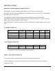
SPECIFICATIONS MAGNETICS PERFORMANCE CHARACTRISTICS Media speed: The circuit decodes data reliably at 3 to 50 inches per second (ips). Card Jitter: The circuit decodes data with bit cell spacing errors up to 15% (30% for subintervals) at media speeds of 3 to 50 ips. Low Amplitude Reading: Media with data recording amplitudes below ANSI and ISO specifications can be read. Media amplitudes of 30% (210 bpi) and higher, or 40% (75 bpi) and higher, can be read at speeds of 10 ips or greater.
ENVIRONMENTAL Operating Temperature: -5°F to 158°F (-20°C to 70°C). Latch units: 32°F to 131°F (0°C to 55°C) Storage Temperature: -40°F to 158°F (-40°C to 70°C). Humidity: Maximum 95% non-condensing. RELIABILITY Magnetic Head Life: 1,000,000 card cycles minimum.* IC Card Connector: 1,000,000 card cycles minimum.* Chassis and Bezel: 1,000,000 card cycles minimum.* Magnetic Read Rate: Less than one error in 100,000 bits on cards conforming to ISO 7811 1-5 (not induced by operator error).
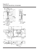
INSTALLATION The ID TECH Hybrid Insert Reader with the standard or metal bezel can be mounted via the front mounting flanges. Side mounting studs are also provided. The reader can be mounted in any orientation, but the preferred position is with the printed circuit board (PCB) on top (so that debris will not accumulate on its surface). It accepts a 26-pin Molex connector 51110-2650 or equivalent for power, ground, and I/O signals. The connector pin-out is provided in Appendix C.
OPTIONAL FEATURES “Gate” Operation A spring-loaded gate protects the bezel opening from dust, dirt, and the insertion of foreign objects, but easily opens to permit card insertion. “Card Latch” Operation The optional “latch” mechanism is available with Standard and Flush-Mount bezels. A TTLlevel control signal controls the mechanism’s operation. It holds an inserted card in place in the reader’s slot until processing has been completed.
Appendix A OUTLINE DRAWING OF READER 6
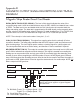
Appendix B MAGNETIC OUTPUT SIGNAL DESCRIPTIONS AND TIMING DIAGRAM Magnetic Stripe Reader/Smart Card Reader DATAx (DATA TRACK LEVEL SIGNAL): The level of this signal indicates the value of the current bit being read. A LOW level data bit has a value of ONE. A HIGH level data bit has a value of ZERO. The data level is true and stable while the CLK (clock) pulse is low and at both the falling and raising edges.
SW (CARD SEATED SIGNAL Pin 10) : Its normal level is HIGH. When the card is fully inserted (seated), the SW signal goes LOW to indicate that all eight contacts on the reader are in full connection with the IC contacts on the smart card. This signal is used to tell the host that the ICC is fully inserted and power can be applied to the smart card contacts.
Appendix C CONNECTOR PIN-OUTS 26-Pin Molex Connector I/O IN IN IN — IN IN I/O —OUT OUT IN IN IN OUT OUT OUT IN OUT IN IN IN OUT OUT OUT OUT OUT PIN 1 2 3 4 5 6 7 8 9 10 11 12 13 14 15 16 17 18 19 20 21 22 23 24 25 26 SIGNAL IC-C1 POWER IC-C2 RESET IC-C3 CLOCK IC-C4 NO DEFINITION IC-C5 GROUND IC-C6 PROG. POWER IC-C7 DATA IC-C8 NO DEFINITION CARD PRESENT* (CP) CARD SEATED* (SW) +5 V SUPPLY (VCC) LATCH CONTROL (LC) CIRCUIT GROUND (GND) N/C M-DATA TK. 2* M-CLOCK TK.