INSTALLATION & MAINTENANCE Commercial & Industrial Sectional Doors Model: ____________________ Serial No.
Dear Ideal Customer, Thank you for purchasing a Ideal Garage Door. Your new Ideal Garage Door was built to meet the highest industry standard and to provide you with years of dependable performance. This manual contains important safety, installation and maintenance instructions. Carefully follow the instructions and maintenance recommendations. Please keep this manual for future reference. If you should require any assistance or additional information, please call Ideal at 1-800-526-4301.
SAFETY INFORMATION I M P O RT A NT ! To Protect Yourself From Injury, Carefully Read The Following Safety Information And Warnings Before You Install Or Attempt To Repair Your New Garage Door • You can install your new garage door yourself IF… 1. you have help (weight can vary from 150 lbs. up to 2,000 lbs.); 2. you have the right tools and reasonable mechanical aptitude or experience; and 3. you follow these instructions very carefully.
SAFETY INFORMATION I M P O RT A NT ! To Protect Yourself From Injury Carefully Read The Following Safety Information And Warnings Before You Install Or Attempt To Repair Your New Garage Door • Track installations must use sway braces on the rear track hangers to prevent sideways movement. If the tracks are not firmly stabilized they might spread, allowing the door to fall and cause severe injury and damage.
IMPORTANT! Before Starting Installation: Things to Know Before You Begin Read the instructions completely before starting the installation of the door. Becoming familiar with the components before assembling the door will reduce the installation time. In the interest of safety this symbol means WARNING or CAUTION. Personal injury and/or property damage may occur unless instructions are followed carefully.
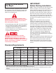
Tools Needed • • • • • • • • • • • “C” Clamps or Locking Pliers Hammer Winding Bars (Torsion Only) Screwdriver Tape Measure Level Socket wrench kit Pliers Drill, and 1/4", 3/16", & 3/8" bits Step ladder Saw horses or other supports for placing section on while assembling Removing the Existing Door Fig. 1-J CONCRETE JAMB (Reverse Angle) Garage doors use springs to balance the door weight. Generally there are two types of springs used — extension springs and torsion springs.
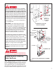
For Torsion Springs Only If your door has a torsion assembly, you must make sure that the wood or steel anchor pad is of good quality, free of cracks or splits, and is firmly attached to the garage wall. (Fig. 1-J) Failure to securely attach the anchor pad could allow the springs to violently pull away from the garage wall, and could result in severe injury and/ or property damage. Under no circumstances should the anchor pad be attached with nails.
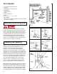
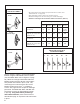
HINGE ILLUSTRATION & ROLLER PLACEMENT #1 Hinge 14 GA. – All center hinges are #1 hinges (except for full vision sections, and Full View doors, see page 13). – Start end hinge sequence at the top of bottom section. – Double end hinges use the same # hinge as outside end hinges. – Rollers in end hinges will use farthest sleeve from section. (FIG. 2-S) End Hinge Top of Each Section Roller 2" Track except as listed below 18 GA.
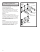
other hurricane prone areas) may require additional reinforcement beyond what is detailed in these instructions. Please refer to engineering drawings for these areas. Strutting Schedule NOTE: All doors do not require struts, follow instructions listed below according to the number of struts supplied. • Number of struts will be shown on hardware box. • All struts are attached with #14 x 3/4" self-drilling screws and struts to center stiles and end stiles.
C-Channel Attachment (Non-Windload Doors Only) Center Stile Or EPS Backer Plate Double End Stile C-Channel If you have a windload door, refer to instructions or drawing provided with door. Insulated Sandwich Doors Only Before installation of hinges, tear the liner off the adhesive on the EPS backer plates and apply vertically across the section at each center hinge location. (FIG.
Lift Handle Instructions Step 2: If you have a 2" thick door, no modifications to the lift handle are necessary. If you have a nominal 2" thick door, remove the (4) tabs at the end of each stem using a pair of pliers. If you have a 13/8" thick door, cut the stems on the lift handle along the ridge line using a hacksaw. (FIG. 5-SA) From the front of the door section, drill (2) 1/2" holes through the section according to the Bottom Section Hole Pattern. (FIG.
Step 7: Top Section. Place top brackets over prepunched holes so they are flush with edge of section. Center of roller carrier will be about 4" down from top of section. Using four #14 x 5/8" hex head sheet metal screws per top bracket, attach top brackets to section. (FIG. 10-S) (Low headroom doors 3/4" refer to Figure 7-T, page 23.) Lock Installation Step 4: The following locking systems are available for commercial steel doors: • Side Lock (FIG. 8-S) • Inside Slide Bolt (FIG. 9-S) 1.
Full Vision and Steel Door If your door has been furnished with one or more full vision sections, please refer to Figure 11-S for identification of the special hinge parts which must be used. End hinges are of the same type and follow the same sequence as described in the general instructions (refer to Figure 2-S, page 8). The standard #14 x 5/8" hex head sheet metal screws are used to fasten the end hinges to the full vision section. See Figure 12-S if you have a full vision top section.
Refer to Figures 12-S, 13-S and 14-S for reinforcement of full vision sections. After full vision sections are in place, refer to the general instructions for completion of your installation. Sometimes, higher than standard wind loading requires a bridge strut (aluminum angle with offset plates). (FIG.
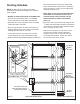
Track Installation General Information. There are three basic pieces of information about your tracks that you need to know to start installation. 1. Track size - Track comes in two sizes: 2" and 3". 3. Type of mounting - Bracket mounting is used on lighter doors with wood jambs. Brackets are loose or riveted into place. Loose brackets are attached to the track with (1) 1/4" x 5/8" track bolt and nut per bracket. Continuous angle and reverse angle track are shipped with mounting angle attached.
Step 1: Vertical Track. Center bottom section in opening on inside of garage. Level section by blocking up low side. (FIG. 2-T) Leave block until door is completed. Install the vertical track on opposite side of where block was placed, over the two rollers of the bottom section with a twisting motion as in Figure 3-T. Raise track 1/2" off the floor, Figure 2-T, and screw 5/16" x 15/8" lags (wood jambs), or self-drilling screws (steel jambs) through bottom mounting bracket. (FIG.
Standard Radius Attach horizontal track to vertical bracket using 1 /4" x 5/8" track bolts and flange nuts. Attach horizontal angle to vertical bracket using 3/8" x 3/4" carriage bolts and flange nuts. Rig a temporary rope to support back of horizontal tracks. They should be level (parallel) to 1" higher in the back when completed. Install top section now to other sections. Refer to Figure 9-S, page 12. (FIG. 5-T) Spring Installation (Page 18) Install and wind springs as explained.
Spring Installation NOTE: All torsion spring doors will be furnished with a Red Warning Label. These labels must be on all spring anchor brackets in plain view. These Warning Labels will be supplied on spring anchor brackets or in the hardware carton. If sticker is missing it is the responsibility of the installer to contact his supplier and have them provide needed warning labels for installation. Spring anchor bracket mounting location. Measure from top of door to center of end bearings.
Spring Winding SPRING TENSION IS DANGEROUS. A sudden release of the springs could result in severe injury. Proceed with caution, following these instructions carefully. Before winding any tension on springs, make sure door is securely locked down with a vise-grip placed on vertical track above a roller. Always use proper size winding bars. Never use screwdrivers or any tool too large or too small. They may break and cause serious injury. Stand to the side of winding bars while winding springs.
ONE SPRING ON STEEL TUBE LEFT WOUND SPRING SHOWN End Bearing Plate Righthand Cable Drum (Black) Left Wound Spring End Bearing Plate Lefthand Cable Drum (Red) 1" O.D.
VIEW “E” Solid Shaft TWO SPRINGS ON A SOLID SHAFT SHOWN Righthand Black Drum End Bearing Plate Solid Shaft Key Inserted Into Left & Righthand Drums Warning Tag Spring Anchor Bracket (2) Set Screws (2) Set Screws Coupler – See View “F” Black Winding Cone Left (Wind Wound CounterSpring clockwise) Spring Anchor Plug (2) Set Screws Lefthand Red Drum – See View “E” Righthand Black Drum With Set Screws – See View “E” 1" O.D.
FOUR SPRINGS ON SOLID STEEL SHAFT DETAIL “A” Warning Tag Spring Anchor Bracket Bearing Bearing Retainer Assemble Typical To Detail “A” End Bearing Plate Righthand Cable Drum Black Winding Cone Wind Counterclockwise As Shown In Detail "C" Black Winding Cone Wind Counterclockwise As Shown In Detail "C" Assemble Typical To Detail “B” Lefthand See Detail “A” – Supplemental Left Center Bearing Wound Support Assembly Spring See Detail “B” – Center Bearing Left Wound Support Assembly Spring 1" O.D.
End Bearing Plate (3) 3/8" Carriage Bolts & Nuts Roller Extension Angle (Cut If Too Long) Horizontal Track Commercial Vertical Bracket Fig. 6-T 3 1 /8 x 1 /4" Slotted Truss Head Bolt & Nut.
Low Headroom Top Brackets All Door Models: Insert rollers in low headroom top brackets. On each side of door, insert each roller into the top horizontal track. Slide each low headroom top bracket down the top section until top section is tight against wood stop or steel jamb. If a top strut has been installed the top bracket will have to be placed between stile and strut. Line each low headroom top bracket up with the side of the top section.
LHR REAR MOUNT TORSION SPRING DOOR — REAR VIEW Right Rear Backhang Center Rear Backhang Left Rear Backhang Spring Anchor Bracket Left End Bearing Plate Left (Black) Winding Cone Right End Bearing Plate Spring Anchor Cones (Red) Right Winding Cone Right Wound Spring Left Wound Spring (Black) Right Hand Cable Drum— See View D below (3) 5/16" x 15/8" Lag Screws (Red) Left Hand Cable Drum— See View C below (Attach to Ceiling Joist) (5) 5/16" x 1" Bolts & Nuts Center Backhang Spring Anchor Bracket
Center Line Of Bearing LHR Front Mount Torsion Spring Doors Attach horizontal track to vertical bracket using 1 /4" x 5/8" track bolts and flange nuts. Attach horizontal angle using 3/8" x 3/4" carriage bolts and flange nuts. The end bearing plate will be positioned and fastened as shown in Figure 11-T. Some drilling in horizontal angle may be required. (FIG. 7-T, page 24) Install springs according to Figure12-T, and wind. See spring winding on page 19 for more information.
Vertical Lift Track Vertical lift tracks are built as one piece or as two pieces per side, depending on door height. Follow the vertical track information (Step 1, page 15) for the lower part of the track, from the floor to the top of the door. Starting at the top of the door, plumb one track and lag or screw it to the wall all the way up. Measure the width of the tracks at the top of the door and set the very top of the second vertical track at the exact same distance.
High Lift Track Some smaller high lift doors will come with vertical tracks in one piece plus the horizontal tracks. Larger high lift doors will have the vertical track in two pieces plus the horizontals. Follow the vertical track information (Step 1, page 16) for the lower part of the track from the floor to the top of the door. Starting at the the door, plumb one vertical track and lag or screw it to the wall all the way up.
Attaching an Automatic Opener To avoid risk of strangulation or personal injury to children, you must remove the pull down rope when you install an automatic garage door operator. Fig. 1-OP NOTE: Failure to reinforce the door as illustrated will void Clopay Warranty. Doors with a stile at center of door: • You will need three pieces of 14 gauge 2" x 2" punched angle iron. Two pieces should be 8 ft. long and one at least 24" long. The 24" piece may have to be trimmed to fit your door. Fig.
section, remove the bottom strut clips and overlap the flange of the strut with the angle iron to secure the bottom of the strut. Attach angle using the fasteners removed with the strut clips. (FIG. 2-OP) • Cut the 24" piece of punched angle iron to span from top horizontal angle to bottom horizontal angle. Place vertical angle directly in the center of the door. Attach vertical angle to both the top and bottom horizontal angles with two 3/8" nuts and two 3/8" bolts. Refer to Figure 3-OP for C-Channel.
Glass Replacement: If your door is equipped with windows and the glass should need replacement, follow the steps below: 1) With someone holding the outside frame, remove the ten screws from the inside window frame. 2) Pull the inside frame out of the door. 3) Carefully remove the broken or old glass. 4) Insert the new (replacement) glass. 5) With someone holding the outside frame, reinsert the screws into the inside frame, trapping the glass. Fig.
NOTE: Swinging portion of Pass Door on bottom section may need to be shimmed up during installation of upper sections to prevent gapping. (FIG. 5-PD) Fra me O (To pen p) ing Fra m (B e Op ott en om ing ) NOTE: To better ensure proper alignment of the frame from section to section, install the center hinges on the gear hinge side of the aluminum pass door frame first and work outwards installing hinges. Install Lock according to Figure 4-PD. Install closer according to the closer instructions provided.