INSTALLATION & MAINTENANCE Steel Residential Garage Door Instructions Model: Size: Serial No.
3DLQWLQJ \RXU 'RRU 3DLQW
Table of Contents Introduction and Opening Preparation STEP 1 – Things to Know Before You Begin ...................................................................................................3 STEP 2 – Read Safety Information ..................................................................................................................4 STEP 3 – Check Headroom, Backroom, Sideroom..........................................................................................
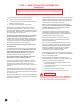
STEP 2 – READ THIS SAFETY INFORMATION IMPORTANT! To Protect Yourself From Injury You Must Carefully Read The Following Safety Information and Warnings Before You Install Or Use Your New Garage Door • You can install your new garage door yourself IF… • a) you have help (it may weigh up to 500 lbs.); b) you have the right tools and reasonable mechanical aptitude or experience; and c) you follow these instructions very carefully. Garage doors use springs to balance them.
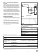
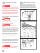
STEP 3 – Check Headroom/ Backroom/ Sideroom Rough Opening = Door Size Backroom = Door Height Plus 18" Headroom is the space needed above the top of the door for the door, the overhead tracks, and the springs. Measure to check that there are no obstructions in your garage within that space. The normal headroom space requirement is shown in Table 3-A. The backroom distance is measured from the back of the door into the garage, and should be at least 18" more than the height of the garage door.
STEP 4 – Removing the Existing Door Springs WARNING Garage doors use springs to balance the door weight. There are two types of springs used — extension and torsion. Each of these is available in either a standard or EZ-SetTM assembly option. Please look at the drawings on page 8 to see which springs your old door has installed. If your present door uses standard torsion springs, do not attempt to remove the door or the springs yourself. They should be removed by a qualified door service professional.
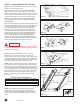
STEP 5 - Removing Door Sections & Track Step 5-1: The door can now be disassembled. Starting with the top section, remove the hardware and unstack the sections one at a time. (FIG. 5-A) Step 5-2: After all sections have been removed from the opening, detach all remaining track and hardware from the jambs.
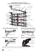
Typical Garage Door Installation Illustration Extension Spring System Shown on Complete Door Rear Track Hanger (Not Included) Containment Cable Extension Spring Stationary Sheave Sheave Door Jamb Horizontal Track Section #4 Flag Bracket Top Bracket #1 Hinge Vertical Track Vertical Track #3 Hinge #3 Hinge Section #3 #2 Hinge #1 Hinge #2 Hinge Safety Label Long Track Bracket Inside Step Plate Section #2 #1 Hinge #1 Hinge Section #1 #1 Hinge Inside Step Plate Safety Label Short Track Brac
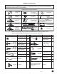
Hardware Components NOTE: All doors will receive (1) spring kit and (1) or more springs. Separate spring installation supplemental instructions should be included with door hardware. This supplement contains a list of all spring related hardware along with instructions on proper spring installation. All Doors Will Receive (2) Of These Items: Track Bracket (Longer) 3/8"-18 x 3/4" Lg.
STEP 7 - Preparing Bottom Door Section Step 7-1: Spread the hardware on the garage oor in groups so that you can easily nd the parts. Step 7-2: Find the section with the aluminum weatherstrip retainer fastened to one edge. The aluminum weatherstrip retainer is on the bottom edge of the bottom section. Place the section on saw horses face down. (FIG. 7-A) Be sure to cover saw horses with carpet or cloth so as not to scratch section. Aluminum Weatherstrip Retainer FIG.
STEP 8 - Lift Handle Attachment 2ND SECTION Bottom Section From the front of the door section, drill (2) 1/2" holes through the section according to the Bottom Section Hole Pattern (FIG. 8-B). A T-Square should be used to ensure that they are vertically in line. If your door has an outside keyed lock, the hole pattern should be drilled on the bottom section directly below the lock.
STEP 9 - Installing Door Sections Step 9-1: Place the section in the opening so that it is against the stop molding and centered from side to side. Place a level on the section and use a piece of wood under one end or the other (if necessary) to make the section level. (FIG. 9-A) Step 9-2: Remove the level and drive a 3” nail in the jambs at each end and bend it over the edge of the section to hold the section in place. (FIG.
STEP 9 - Installing Door Sections (Continued) Step 9-6: Place the second section on top of the rst section. Drive a 3” nail in the jambs at each end and bend it over the edges of the section to hold the section in place. Attach the hinges from the top of the rst section to the bottom of the second. (FIG. 9-D) Safety Label Step 9-7: Place the third section on saw horses. Attach #3 hinges to the ends at the top edge and #1 hinges to all other stiles along the top edge using #14 x 5/8” sheet metal screws.
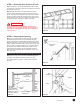
STEP 10 - Reinforcing the Top Section for Opener To avoid damage to your door, you must reinforce the top section of the door in order to provide a mounting point for the opener to be attached. You will need one (1), two (2), or three (3) pieces of 1-1/4” x 1-1/4” minimum punched angle at least 13 gauge or 3/32” thick from your local hardware or building supply store. Figures 10-B to 10-E show how punched angle is to be afxed to door.
STEP 11 – Assembling and Installing the Track Before assembling brackets to vertical track be sure to read Step 11-1 and Step 11-2. Refer to illustration for placement of brackets on track. NOTE: Brackets may already be riveted in place. If additional adjustment is required, the rivets can be drilled out and the brackets can be reattached with track bolts and flange nuts (available through the toll-free Consumer Services number, see outside cover).
STEP 11 - Assembling and Installing the Track (Continued) NOTE: Pressure-treated lumber purchased after January 2004 is treated with chemicals that have highly corrosive effects on metal fasteners. The fasteners provided with your door are intended for use with standard lumber (not pressure-treated) only.
Step 11- 8, Continued: Adjust the position of the tracks if the squareness distances are not within 1/2" of each other. Horizontal track can be out of level up to 1" from front jamb to rear track hanger. (FIG. 11-I) When the track is square and level with the opening, the track hangers can be fastened permanently to the ceiling trusses. Three 5/16" x 1-1/2" lag screws are recommended. Be sure 3/16" pilot holes are drilled before installing 5/16" lag screws.
STEP 15 – Attaching an Automatic Opener IMPORTANT: To avoid damage to your door, you must reinforce the top section of the door in order to provide a mounting point for the opener to be attached. Refer to the section of this manual titled Reinforcing the Top Section on page 14 for specific instructions. Failure to reinforce the door as illustrated will void the warranty on your door.
3DLQWLQJ \RXU 'RRU 3DLQW
$QQXDO 0DLQWHQDQFH &OHDQLQJ WKH 'RRU /XEULFDWH DOO PRYLQJ SDUWV RI WKH GRRU ZLWK OLJKW KRXVHKROG RLO LQFOXGLQJ D /LIW FDEOHV DW WKH ERWWRP EUDFNHW EXWWRQ E %HDULQJ RI WKH VKHDYHV F /RFN KDUGZDUH ZKHUH VXUIDFHV WXUQ RU VOLGH G )XOO OHQJWK RI WRUVLRQ VSULQJ WR UHGXFH IULFWLRQ EHWZHHQ FRLOV H /XEULFDWH VWHHO UROOHUV '2 127 OXEULFDWH Q\ORQ UROOHUV ,Q RUGHU WR SUHYHQW GDPDJH UXVWLQJ FDXVHG E\ IRUHLJQ PDWWHU DGKHULQJ WR WKH GRRU WKH GRRU VKRXOG EH FOHDQHG DW OHDVW WZLFH D \HDU