#45-930 #45-935 Shielded Twisted Pair (STP) Cable Stripping System For 115V or 230V Operation Manual
Shielded Twisted Pair (STP) Cable Stripping System Table of Contents Introduction ..................................................................... Caution and Safety Instructions ....................................... Environmental Conditions ............................................... Warranty & Service Policy ............................................... Unpacking........................................................................ STP Service Setup .........................................
Caution and Safety Instructions Please read, understand and follow the warnings and instructions in this manual. Failure to do so can result in serious personal injury. • Do not alter, modify or misuse the machine. • Do not operate the machine using an ungrounded electrical system. • Do not perform any maintenance on the machine unless both the electrical power and air supply are disconnected. • Do not operate the machine in a damp, wet, gaseous, hazardous or poorly ventilated work environment.
STP Service Setup Continued Electrical Connection Requirements Voltage Selection The STP operates on either 115V/230V AC; 45-930, 115V AC 4A 60 Hz ; 45-935, 230V AC 2A 50 Hz. Proper voltage will be preset at the factory. Fuse Replacement Disconnect power cord and remove the fuse cartridge using a small blade screwdriver or similar tool. Replace two fuses with recommended fuses.
STP Operating Principles and Terms (continued) SPEED: Thermal Head Rotation SPEED refers to the rate of rotation by the Thermal Head of the STP. This is the rate at which the blades are rotated about the wire being stripped. The slowest speed is 1 and 10 the highest. Running at a faster speed requires a higher blade heat setting which may shorten the blade life. A superior strip quality is obtained at lower blade HEAT and SPEED settings.
STP Operation continued Heat Adjustment Heat can be adjusted by pressing [0] through [9] producing corresponding heat values of 0% through 90%. Pressing HIGH sets the heat at 100%. If the heat is set at 0%, the machine completes the cycle without using the blades. The heat can also be adjusted by pressing HEAT and using the [ ↑ ] and [ ] keys. The heat is adjusted from 0% to 100% in increments of 10%. Pressing the ENTER key exits from the heat entry mode and returns to the ready mode.
STP Operation continued Strip Length Adjustment, by Discrete Value For Example Enter Value of 75 mm: METRIC LENGTH MODE (31 mm to 152 mm) • Press STRIP LENGTH. • The strip length display will blink. • Enter the strip length and then press ENTER. A strip length is automatically entered after a third digit is pressed. 20% 10 STRIP LENGTH ENTER 40 0 ENTER VALUE Press Press Numbers 7 Then 5 Digit Will Blink Press ENGLISH LENGTH MODE (1-1/4 inches to 6.00 inches) • Press STRIP LENGTH.
STP Operation continued TWO STAGE CYCLE The TWO STAGE CYCLE is intended to break the STP’s stripping cycle into two separate stages; stage one is for cutting, stage two is removal. When the cable is inserted, the first stage will thermally cut the insulation. When this stage is completed and the cable is removed, the cable can be inspected for a complete cut, or the cable can be flexed to insure a complete cut has been achieved.
STP Operation continued Slug Removal SINGLE CYCLE The STP can be used to remove the slug without applying heat to the blades, if the insulation has already been severed. This is accomplished by pressing “0” when the unit is in the “READY MODE”. The next cycle will run with zero heat and act only as a slug removal machine. When this cycle is completed, the STP returns to the previous settings.
STP Operation continued Set Mode 1—INCR 2—CODE 3—UNIT 4—LOCK OUT 5—COUNT 1 — STRIP LENGTH INCREMENT SET STRIPLENGTH SET STRIPLENGTH INCREMENT 0.00 IN INCREMENT 0 MM This allows programming the strip length in increments by using the arrow keys to increase or decrease the length appearing on the display. ENGLISH LENGTH MODE - (0.01 in. to 0.99 in.) The tenths position begins blinking. After the tenths digit is entered, the hundredth position blinks.
STP Operation continued Batching Storing a Batch ENTER IN 3-DIGIT • Press BATCH SECURITY CODE • Press PROGRAM Press Press • Enter the 3-digit security code • Enter in the batch number for storage • Press ENTER All of the current inputs are then stored in this batch. Press CLEAR to exit to the ready mode. ENTER IN BATCHING PRGM. BATCH HIGH — NUMBER ENTER 0 Press Retrieving a Batch ENTER IN BATCHING • Press BATCH NUMBER 0 Press Press • Enter in the batch number to be retrieved.
STP Service continued 3 — GRIP BACK SENSOR (senses if the pull cylinder is back) 4 — TRIGGER SENSOR (senses if the trigger is being pressed) 5 — WIRE OUT SENSOR (senses if the wire is out of the insertion hole) 6 — SENSOR TEST OFF (turns all sensor tests off) If a sensor test is enabled a tone sounds when the test conditions are present. When a sensor test is enabled all other sensor tests are disabled. To return back to the test mode, press CLEAR.
STP Operation continued Gripper Pad Replacement The STP has two sets of grippers. The front grippers hold the wire while the rear grippers pull off the slug. Both sets of grippers have pads that require periodic replacement. NOTE: To replace pads press caps firmly in place, then use a small screwdriver to pop up the tops so they catch on the inner shoulder of gripper. REAR GRIP PAD ASSEMBLY FLAT TABS MUST ALIGN WITH GRIPPER PIN HOLE.
STP Service continued Rear Gripper Pad Replacement 1. 2. 3. Disconnect power Disconnect air Open case 4. Caution blades may be hot. 5. Move pull cylinder all the way forward. This allows removal of the gripper pads toward the rear. *Pull out grip pins. Moveable gripper has 3 grip pins. Stationary gripper has 1 pin. 6. Remove grippers. Stationary gripper slides straight out. Movable gripper must be removed from cylinder adapter and then slid straight out.
STP Service continued Blade Replacement 1. 2. 3. 4. 5. Electronically set strip length to 6". This moves the stop bar all the way back allowing more room to replace the blades. Disconnect power. (rear gripper will retract all the way back). Disconnect air. Open lid. Note: Open lid by pressing button and lifting lid. Unplug blade electrical connection and cut off connector (a new connector is supplied with replacement blade set). CUT OFF CONNECTOR 6. Remove the two hold-down clamps. 7.
STP Service continued Blade Replacement 9. Remove the four #4-40 socket head screws positioning blades. 11. Reverse the process by feeding the new blade wires through the holes and silicone tubes. 12. Replace the four #4-40 socket head screws for positioning blades. 13. Connect the two short leads inside silicone tube. 14. Pass the two long leads through the long silicone tube and plug into its electrical connection. NOTE: alignment of connector pin. 15.
STP Service continued CPU Module Replacement CPU MODULE The CPU Module (Central Processing Unit) and the Power Module are not field repairable, they must be returned to IDEAL for service. The CPU is located behind the faceplate on the inside of front lid. 1. Disconnect power. 2. Disconnect air. 3. Open front lid all the way so that it rests on top of rear cover. 4. Remove the six #8-32 button head screws from faceplate.
STP Service continued Preventative Maintenance The STP requires very little maintenance aside from changing blades and gripper pads. Visually inspect threaded rods and guide rods. If they look dry, lubricate with a light machine oil. Remove slug debris from unit. Replace nylon cable chains (2) as required. OIL RODS WHEN DRY Cleaning Your STP Note: Disconnect power and air when cleaning the unit. Clean front gripper pads and holder with rubber roller cleaner.
*Refer to Sub Assemblies with their own parts lists on pages 16 and 17. STP Machine Assembly Item 1 2 3 4 5 6 7 8 9 10 11 12 13 14 15 16 17 18 19 20 21 22 23 24 Strip Length Count Clear Pragm. High Speed Heat Pressure 8 LEN PSI SPD 90 Enter Name Assy, Control Module Assy, Front Gripper Assy, Thermal Head Assy, Case Assy, Rear Gripper Assy, Strip Length Adj.
5 2 3 20 Item 1 2 3 4 5 Qty 1 1 1 1 1 Name Assy, Interface Board Assy, Pressure Regulator Air Solenoid Assy, Power Supply Air Reservoir Top Shelf Assembly Part No. K-7468 K-7749 392.002 IA3273 392.005 1 4 4 1 Qty 6 ft 6 ft 3 1 Item 1 2 3 4 1 1 2 Name Tubing .250" O.D. (Red) Tubing .125" O.D. (Red) Tubing Coiled .125" O.D. (2 hole) (Black) Air Hose Air Tubing 3 K-6865 543.052 Part No. 543.048 543.
10 9 7 Qty 2 1 1 2 1 2 1 2 3 7 11 4 3 6 4 Name Front Grip Block Wire Entry Guide Cylinder Adapter Spacer, Stop Sensor Plate Front Grip Pad Cylinder Pin, Gripper 5 1 5 2 6 12 8 8 2 Part No. LA2381 LA2382 LA2394 LA2397 LA2406 LA2408 391.
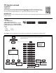
` 5 WIRE ENTRY GATE SENSOR CHASSIS GROUND CONNECTION 120/240 VAC INPUT 15 1 2 3 H1 1 2 3 27 POWER INPUT MODULE 17 STRIP LENGTH STOP SENSOR 1 4 3 2 14 1 13 25 TRANSPORT HOME SENSOR 16 3 1 2 1 2 3 4 H5 1 2 H5 1 2 3 4 H1 BLADE HOME SENSOR AC WIRING BOARD ASSEMBLY 1 2 3 4 11 H2 1 2 3 4 H4 1 2 3 4 H3 8 CPU PCB ASSEMBLY 1 2 3 4 1 2 3 4 1 2 3 4 21 21 1 2 3 4 5 6 7 8 9 10 11 12 13 14 15 16 17 18 19 20 21 22 23 24 25 26 27 28 29 30 31 32 33 34 H4 REAR GRIP SOLENOID
Warranty limited solely to repair or replacement; no warranty of merchantability, fitness for a particular purpose or consequential damages. 1000 Park Avenue, Sycamore, IL 60178 – Manufacturing Facility Form No. ND 3514-1 ©2002 IDEAL INDUSTRIES, INC. IDEAL INDUSTRIES, INC. Becker Place, Sycamore, IL 60178 – 800-435-0705 in U.S.A. Ajax, Ontario, L1S 2E1, Canada – 800-527-9105 in Canada Warrington, Cheshire WA5 5TN, England – 44 1925 444.446 www.idealindustries.com Rev. 4/02 Printed in U.S.A.