IDEAL INDUSTRIES, INC. TECHNICAL MANUAL MODEL: 61-095 The Service Information provides the following information: • Precautions and safety information • Specifications • Performance test procedure • Calibration and calibration adjustment procedure • Basic maintenance (cleaning, replacing the battery) Form number: TM61095 Revision: 2.
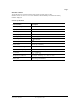
TABLE OF CONTENTS Page # 1 1 1 Title Introduction Precautions and Safety Information Symbols Safety 2 Specifications 3 General Specification 3 Voltage Specifications 4 Resistance and Continuity Specifications 4 Current Specifications 4 Physical and environment characteristics 5 Certification and compliance 5 Required Equipment 6 7 Basic Maintenance Opening the Meter Case 7 Replacing the Battery 7 Cleaning 7 8 Performance Tests Testing the Voltage Function 8 Testing the Resistance
Page 1 Introduction Warning To avoid shock or injury, do not perform the verification tests or calibration procedures described in this manual unless you are qualified to do so. The information provided in this document is for the use of qualified personnel only. Caution The 61-095 contains parts that can be damaged by static discharge. Follow the standard practices for handling static sensitive devices. For additional information about IDEAL INDUSTRIES, INC.
Page 2 SAFETY Review the following safety precautions to avoid injury and prevent damage to this product or any products connected to it. To avoid potential hazards, use the product only as specified. CAUTION. These statements identify conditions or practices that could result in damage to the equipment or other property. WARNING. These statements identify conditions or practices that could result in personal injury or loss of life. Specific precautions Do not operate without covers.
Page 3 SPECIFICATIONS All specifications are warranted unless noted typical and apply to the 61-095. Stated accuracies are at 23ºC ± 5ºC at less than 80% relative humidity and without the battery indicator displayed. General specifications Characteristics Description LCD display digits 3½ Display count 2,000 Numeric update rate 2.
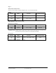
Page 4 Measurement Characteristics Accuracy is ±(% reading + number of digits) at 23ºC ± 5ºC, less than 80% R.H. Voltage Function Range Accuracy Overload protection V 600 Vrms ± (1.5%+ 3 dgt) 40Hz ~ 500Hz 600 Vrms V 600 V ± (1% + 2 dgt) Input impedance: 1MΩ // less than 100pF. Resistance & Continuity Function Ω Range Accuracy Overload protection 2000 Ω ± (1% + 2 dgt) 600 Vrms Max.
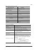
Page 5 Physical and Environmental Characteristics Physical Characteristics Description Dimensions (H x W x D) 188mm x 66mm x 42mm Weight (with battery) 0.3Kg Environmental Characteristics Temperature operating Non-Operating Description 0 to + 50ºC -20 to + 60ºC Humidity (operating) < 80% R.H. Altitude Operating 2,000 m (6560 ft.) Non-Operating 12,300 m (40354 ft.) Vibration & shock Operating MIL-T-28800E (5 ~ 55Hz, 3g maximum) Conductor Size 12mm (0.
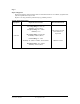
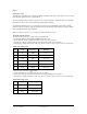
Page 6 Required Equipment Required equipment is listed in Table B. If the recommended models are not available, equipment with equivalent specifications may be used. Repairs or servicing should be performed only by qualified personnel. Table B. Required Equipment Equipment Required Characteristics AC Voltage Range: 0-750V AC Accuracy: ±0.07% (Basic) Frequency Range: 40 ~ 500Hz Accuracy: ± 2% Calibrator DC Voltage Range: 0-1000V DC Accuracy: ±0.
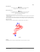
Page 7 Basic Maintenance Warning To avoid shock, remove the test leads and any input signals before opening the case or replacing the battery or fuses. Opening the Meter Case Caution To avoid unintentional short circuit, always place the uncovered meter assembly on a protective surface. When the case of the meter is open, circuit connections are exposed. To open the meter case, refer to Figure 1 and do the following: 1.
Page 8 Performance Tests The following performance tests verify the complete operability of the meter and check the accuracy of each meter function against the meter’s specifications. Accuracy specifications are valid for a period of one year after calibration, when measured at an operating temperature of 18ºC to 28ºC and at a maximum of 80% relative humidity. To perform the following tests, it is not necessary to open the case; no adjustments are necessary.
Page 9 Testing the Resistance Function To verify the accuracy of the resistance function, do the following: 1. Connect the calibrator to VΩ and COM on the meter. 2. Turn the rotary switch to Ω. 3. Apply the inputs for step 1-4 in Table 3. 4. Compare the meter display readings to the display readings in Table 3. 5. If the display reading falls outside of the range shown in Table 3, the meter does not meet specification.
Page 10 O K Figure 2 Top shows correct method; bottom shows incorrect method. Calibration Calibrate the meter once a year to ensure that it performs according to specifications. Perform calibration at an ambient temperature of 23ºC ± 2ºC and relative humidity of 75% or less. Calibration for the Model 61-095: 1. Disconnect the test leads from any circuit under test and turn off tester. 2.
Page 11 Figure 3 - Calibration Adjustment Points Form number TM61095 Rev 2 September 2002