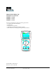
IDEAL INDUSTRIES, INC. TECHNICAL MANUAL MODEL: 61-320 MODEL: 61-322 MODEL: 61-324 The Service Information provides the following information: • Precautions and safety information • Specifications • Performance test procedure • Calibration and calibration adjustment procedure • Basic maintenance (cleaning, replacing the battery and fuses) Form Number: TM61320-2-4 Revision: 2.
TABLE OF CONTENTS Page # 1 1 1 Introduction Precautions and Safety Information Symbols Safety 2 Specifications 3 General Specification 3 Voltage Specifications 4 Current Specifications 5 Resistance, Diode, Continuity Specifications 5 Capacitance, Frequency Specifications 6 Physical and environment characteristics 7 Certification and compliance 7 Required Equipment 8 9 Basic Maintenance Opening the Meter Case 9 Replacing the Battery 9 Testing Fuses 10 Replacing Fuses 10 Cleaning
Page 1 Introduction Warning To avoid shock or injury, do not perform the verification tests or calibration procedures described in this manual unless you are qualified to do so. The information provided in this document is for the use of qualified personnel only. Caution The 61-320, 61-322, and 61-324 contain parts that can be damaged by static discharge. Follow the standard practices for handling static sensitive devices. For additional information about IDEAL INDUSTRIES, INC.
Page 2 SAFETY Review the following safety precautions to avoid injury and prevent damage to this product or any products connected to it. To avoid potential hazards, use the product only as specified. CAUTION. These statements identify conditions or practices that could result in damage to the equipment or other property. WARNING. These statements identify conditions or practices that could result in personal injury or loss of life. Specific precautions Use proper Fuse.
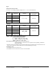
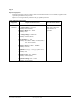
Page 3 SPECIFICATIONS All specifications are warranted unless noted typical and apply to the 61-320, 61-322 and 61-324. Stated accuracies are at 23ºC ± 5ºC at less than 80% relative humidity and without the battery indicator displayed. General specifications Characteristics Description Display count 6,000 Numeric update rate 1.
Page 4 Measurement Characteristics Accuracy is ± (% reading + number of digits) at 23°C ± 5°C, less than 80% R.H. DC Volts Range Resolution 600.0mV 100µV 6.000V 1mV 60.00V 10mV 600.0V 100mV 1000V 1V Accuracy Over voltage protection ±(0.5% + 2dgt) 1000V rms Over voltage protection AC Volts Range Resolution Accuracy 600.0mV 100µV Unspecified 6.000V 1mV 60.00V 10mV 600.0V 100mV ±(0.9% + 5dgt) 50Hz ~ 500Hz * 1000V rms 750V 1V Input Impedance: 10MΩ // less than 100pF.
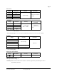
Page 5 DC Current Range Resolution 600.0µA 1mV 6000µA 1mV 60.00mA 10mV 600.0mA 100mV Accuracy Over voltage protection ±(1.0%+2 dgt) 600V rms1A (600) Fast blow fuse AC Current Range Resolution 600.0µA 1mV 6000µA 1mV 60.00mA 10mV Accuracy Over voltage protection ±(1.5%+2 dgt) 50Hz ~ 500Hz * 600V rms 1A (600) Fast blow fuse 600.0mA 100mV Voltage Burden: µA: <4mV / µA mA: 2V max. * AC Conversion Type: Conversion type and additional specification are same as DC/AC Voltage.
Page 6 Frequency Range Sensitivity Accuracy Overload protection Frequency : 0.01%±1digit 600V rms 6000Hz 60.00KHz 100mV rms * 600.0KHz 6.000MHz 250mV rms 60.00MHz 1V rms * Less than 20Hz, the sensitivity is 1.5V rms. Capacitance Accuracy Overload protection ±(1.9% + 8 dgt) 600V rms Range 6.000nF 60.00nF 600.0nF 6.000µF 60.00µF 600.0µF 6.000mF * * < 100 dgt of reading rolling.
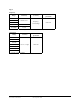
Page 7 Physical and Environmental Characteristics Characteristics Dimensions (H x W x D) Description 158mm x 76mm x 38mm 164mm x 82mm x 44mm (with holster) Weight (with battery) 0.3Kg With holster 0.5Kg Environmental Characteristics Temperature operating Non-Operating Description 0 to + 50ºC -20 to + 60ºC Humidity (operating) < 80% R.H. Altitude Operating 2,000 m (6560 ft.) Non-Operating 12,300 m (40354 ft.) Vibration & shock Operating MIL-T-28800E TYPE II Class 5 2.
Page 8 Required Equipment Required equipment is listed in Table B. If the recommended models are not available, equipment with equivalent specifications may be used. Repairs or servicing should be performed only by qualified personnel. Table B. Required Equipment Equipment Calibrator Required Characteristics AC Voltage Range: 0-750 VAC Accuracy: ±0.07% (Basic) Frequency Range: 40 ~ 1KHz Accuracy: ±2% DC Voltage Range: 0-1000V DC Accuracy: ±0.
Page 9 Basic Maintenance Warning To avoid shock, remove the test leads and any input signals before opening the case or replacing the battery or fuses. Opening the Meter Case Caution To avoid unintentional short circuit, always place the uncovered meter assembly on a protective surface. When the case of the meter is open, circuit connections are exposed. To open the meter case, refer to Figure 1A and do the following: 1.
Page 10 Testing Fuses To test the internal fuses of the meter: 1. Turn the rotary selector switch to the Ω position. 2. To test FS1, plug a test lead into VΩHz input terminal and touch the probe to the mA input terminal. The display should indicate between 0.0 to 0.2 Ω. FS1 (1A 600V - Bussmann BBS-1 recommended). If display reads higher than 0.2Ω, replace the fuse.
Page 11 Performance Tests The following performance tests verify the complete operability of the meter and check the accuracy of each meter function against the meter’s specifications. Accuracy specifications are valid for a period of one year after calibration, when measured at an operating temperature of 18ºC to 28ºC and at a maximum of 80% relative humidity. To perform the following tests, it is not necessary to open the case; no adjustments are necessary.
Page 12 Table 1 AC Voltage Test: Step Input Frequency Reading 1 5.800V 50Hz 5.743 to 5.857 2 5.800V 500Hz 5.743 to 5.857 3 58.00V 50Hz 57.43 to 58.57 4 58.00V 500Hz 57.43 to 58.57 5 580.0V 50Hz 574.3 to 585.7 6 580.0V 500Hz 574.3 to 585.7 7 750V 50Hz 738 to 762 8 750V 500Hz 738 to 762 6. Turn the rotary switch to “V ” position. 7. Set the calibrator for the voltage from step 1 to 6 in Table 2. 8.
Page 13 Testing the Capacitance Function The meter measures capacitance by charging the capacitor with a known direct current, measuring the resultant voltage, and calculating the capacitance. If the same capacitance is measured on an impedance bridge, a different reading may result. This variance is likely to be greater at higher frequencies. To verify the accuracy of the capacitance measuring function, do the following: 1.
Page 14 Table 5 AC mA Test: Step Source Frequency Reading 1 58.00mA 50Hz 56.93 to 59.07 2 58.00mA 500Hz 56.93 to 59.07 3 580.0mA 50Hz 569.3 to 590.7 4 580.0mA 500Hz 569.3 to 590.7 6. Turn the rotary switch to mA . 7. Apply the inputs for steps 1-2 in Table 6. 8. For each input, compare the reading on the meter display to the reading in Table 6. 9. If the display reading falls outside of the range shown in Table 6, the meter does not meet specification.
Page 15 Table 8 Frequency Test: Step Source Level Reading 1 5.600KHz 100mV rms 5.598 to 5.602 2 56.00KHz 100mV rms 55.98 to 56.02 3 560.0KHz 100mV rms 559.8 to 56.02 4 5.600MHz 250mV rms 5.598 to 5.602 5 56.00MHz 1V rms 55.98 to 56.02 Calibration Calibrate the meter once a year to ensure that it performs according to specifications. Perform calibration at an ambient temperature of 23ºC ±2ºC and relative humidity of 75% or less Calibration for the Model 61-320, 61-322 and 61-324: 1.
Page 16 Figure 3 - Calibration Adjustment Points Form number TM61320-2-4 Rev 2 September 2002
Page 17 Form number TM61320-2-4 Rev 2 September 2002