Buccaneer GT Combination Boiler Falcon GTE Combination Boiler Installation, Assembly and Servicing Oil or Gas Fired Boilers Assembly and Installation Instructions for Ideal Buccaneer and Falcon Oil or Gas Fired heating combination boilers should be read in conjunction with the Boiler Assembly Instructions enclosed and any other technical publication supplied with the burner.
WARNING The boiler shall be assembled and installed by a qualified professional only. Strict compliance with these assembly, installation and maintenance instructions is a precondition for the correct operation of the boiler 1. Contents 1. General ........................................................................ 2 1.1 Technical Specifications of Combination Boilers .. 3 1.2 Main Dimensions ..................................................
1.
GENERAL 1.
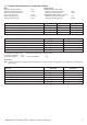
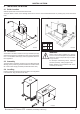
INSTALLATION 2. INSTALLING THE BOILER 2.1 Boiler Location Sufficient space shall be left clear around the boiler. The figure stated in metres in the drawings below are the minimum recommended dimensions for providing easy access around the boiler. Buccaneer GT Falcon GTE 1357 0 .5 m 10 0. 5 30 60 0.5 m 0 m GTE 4/150 I 5/150 I 1m 4/250 I BUC5001 5/250 I L1 H 1180 1537 1424 1587 BUC5038 2.
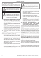
INSTALLATION 2.5 Hydraulic Connections WARNING Installation must be carried out following the regulations in force, trade practices and the recommendations contained in this leaflet. If the distribution pipework is in copper, a sleeve in steel, cast iron or insulating material must be placed between the hot water outlet of the unit and this pipework so as to avoid any corrosion at the level of the branch pipe.
INSTALLATION 2.8 Example of Installation The boiler-to-tank connection kit is placed between points A and B between the boiler and the heating circuit. Example: Buccaneer GT ! " # $ " # $ $ % % & % # ' () # ' * '$ () # ' * $ '$ " + # '$ ' , - $ % % ! + ! .
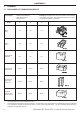
ASSEMBLY 3 ASSEMBLY 3.1 BUCCANEER GT COMBINATION BOILER Tools required: Boiler Boiler Body - Phillips head screwdriver - Wide flat screwdriver - 13mm spanner Packaging: the tables below show the numbers of the packages which make up the boiler. The packages are listed in the order in which they are opened for assembly.
ASSEMBLY 1 Package IC1, IC2, IC3 À Á A BUC5010 *7+# Â Ã 2 1 2 2 1 *7+# ! 1 2 1 *7+# Assembling the base and draining tube 1. 2. 3. Lay a sheet of paper in front of the boiler body, take the boiler body off the pallet and place it standing on the furnace door. Remove the adjustable feet assembled on the base and replace them with the four protective plastic plugs supplied in connection kit package BH 46. Unscrew 1/2" plastic plug A from the rear section of the boiler body.
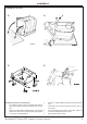
ASSEMBLY 2 Assembling the boiler onto the tank - Place the boiler on the tank so that it is positioned on the first two marks on the front of the tank. - Assemble the boiler as instructed in views 3 - 13 of Buccaneer GT boiler Assembly Instructions. 3/4" tubes BUC5014 14 15 * *7+# $ Installing the pipes - 10 Connect the pipes between boiler and tank (package BH 46) - see the instructions on page13.
ASSEMBLY 3.2 FALCON GTE COMBINATION BOILER Tools required: - Phillips head screwdriver - Wide flat screwdriver - 13mm spanner Boiler Packaging: the tables below show the numbers of the packages which make up the boiler. The packages are listed in the order in which they are opened for assembly.
ASSEMBLY 37 38 Assemble the boiler as instructed in figures 1 - 16 * BUC5041 Assembling the boiler on the hot water tank - Place the boiler on the tank if required with a handling tool (if required). Assembly the boiler as instructed in figures 17 - 33 of boiler assembly instructions for Falcon GTE. Installing the tubes - Connect the tubes between boiler and tank (package BH 46) as directed in the instructions on page 13.
ASSEMBLY 3.3 Hydraulic Boiler to Tank Connections Kit (BH46) Assembly 17 16 A 14 E 9 13 11 7 C B 13 14 D E 14 10 12 11 14 4 5 E 3 (V) 5 1 A. B. ! " C. # $ % " 11 D. # $ & " " (P) ' " " ' ( " " ) ** + Connection kit BH46, provides connections from the tank to the boiler.
ASSEMBLY 4. CONTROLS The boiler connections shall be performed by a qualified professional only. 4.1 Description Strict compliance with these operating and connecting instructions is a precondition for the correct operation of the boiler 9 6 10 7 2 3 6 5 7 4 8 3 9 TEST STB 30 AUT o c 6,3 AT BUC5037 8 / Off 4 1. On switch. 2.
ASSEMBLY 4.3 Electrical Connections The electrical wiring has been carefully checked in the factory and the internal connections of the control panel must not be modified in any event. The electrical connections of the boiler shall be made in compliance with applicable standards and regulations in force. The unit shall be powered by a circuit with an omnipole switch with an opening distance greater than 3 mm.
ASSEMBLY - Install domestic hot water sensor cable A (e.g. for Buccaneer GT) as shown and fix it with plastic clips B. - Insert the sensor in the thimble tube of the tank. Tank Sensor - Connect as directed in the diagram on the following pages. - Insert the bulb of the limiting thermostat in the thimble tube on the rear of the boiler. Boiler Sensor BUC5043 BUC5044 4.
ASSEMBLY 1. Instructions for use Regulating the storage temperature of hot water for sanitary systems: 3 6 2 In the event of prolonged absence: 7 1 In order to ensure that the sanitary hot water tank is protected against frost, set the regulating button A to the position 1 (this setting corresponds to a temperature of about 10ºC). 2.
ASSEMBLY - Introduce the bulb G of the limiter thermostat into the boiler pocket. - Connect the charging pump to the boiler control console, ensuring that the terminals live (L), neutral (N) and earth ( ) are properly attached. - Connect the probe bulb to the boiler control console. - Introduce the probe bulb into the pocket of the sanitary hot water tank.
ASSEMBLY 4.6 Heating and Domestic Hot Water Installation (with MB1 module) WARNING IMPORTANT: If the installation includes an MB1 module and no room thermostat (TAM), set three position switch 5 (see page 14) to . If the installation includes an MB1 module and a room thermostat (TAM), set three position switch 5 (see page 14) to AUTO.
ASSEMBLY 5. COMMISSIONING (P)* (O) (A) - Ensure connections are watertight. - Vent the tank heat exchanger as follows: 1. Unscrew the auto vent cap (P)* a few turns. 2. Turn the antisyphon valve screw 10 to open position (O) 3. Close the vent (P)* when water flows continuously. 4. Return the antisyphon valve screw 10 to the automatic position (A) 5.
SERVICING 6. MAINTENANCE AND PERIODIC CHECKS • • Safety valve or group The magnesium anode must be checked at least every two years. Starting with the first check and taking account of the wear to the anode, the frequency of the following checks must be decided. The anode can be checked according to one of the following two methods: WARNING IMPORTANT: The safety unit must be used periodically (at least once per month). To do this, place the safety group in the draining position.
NOTES 22 Buccaneer GT, Falcon GTE - Installation, Assembly & Servicing
NOTES Buccaneer GT, Falcon GTE - Installation, Assembly & Servicing 23
Caradon Plumbing Limited, P.O. Box 103, National Ave, Kingston upon Hull, HU5 4JN. Telephone: 01482 492 251 Fax: 01482 448 858. Registration No. London 322 137. Technical Training The Caradon Plumbing Limited Technical Training Centre offers a series of first class training courses for domestic, commercial and industrial heating installers, engineers and system specifiers. For details of courses please ring: ...............