installation and servicing classic Your Ideal installation and servicing guide See reverse for classic users guide For details of document amendments, refer to page 3 HE9, HE12, HE15, HE18 When replacing any part on this appliance use only spare parts that you can be assured conform to the safety and performance specification that we require. Do not use reconditioned or copy parts that have not been clearly authorised by Ideal Boilers.
classic HE - Installation & Servicing 2 201850-6.
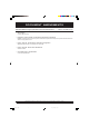
DOCUMENT AMENDMENTS Relevant Installation changes implemented in this book from Mod Level ............ A05 (Oct 06) to A06 (Jan 08) • Various Pages Company Name Change. • Page 26 & 27, Frames 39 & 40 - Condensate Pipe Termination Configurations BS6798 recommends that a second trap and an air break are required where the siphon trap within the boiler is less than 75mm for configuration 2 and 3 • Page 27, Frame 40 - Condensate Pipe Termination Configurations Statement added with ref.
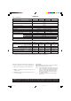
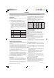
GENERAL Table 1 - General Data Boiler Size HE9 Gas supply connection HE12 (in. BSP) HE15 HE18 Rc 1/2 (1/2) 1/2" (BSP Female) Flow connection 22mm copper Return connection 22mm copper Maximum static water head m (ft.) 30.5 (100) Minimum static water head m (ft.) 0.45 (1.5) Electrical supply 230 V 50 Hz Boiler power consumption; 100W Fuse rating External; 3A Water content litre (gal.) Internal; F1A to BS.4265 3.0 (0.67) 3.95 (0.
GENERAL classic HE CONTENTS Natural Gas only Boiler size G.C. Appliance No. (Benchmark No.) PI No. 41-415-58 41-415-59 41-421-45 41-421-46 87 BQ 10 87 BQ 10 87 BQ 10 87 BQ 10 HE9 HE12 HE15 HE18 Destination Countries: GB, IE Air Supply. ..................................................................... 9 Benchmark Commissioning Checklist ..................... 46 Boiler Clearances ......................................................... 7 Boiler Exploded View ....................................
GENERAL INTRODUCTION The classic HE 9, 12, 15 and 18 are a range of automatically fully controlled, wall mounted, balanced flue, fanned, high efficiency, condensing gas boilers. The primary heat exchanger is cast iron. The secondary heat exchanger is aluminium. The boiler casing is of white enamelled mild steel. The boiler casing has a removable controls pod containing a drop-down door. The boiler thermostat is located behind the drop- down door. Note.
GENERAL 1 BOILER WATER CONNECTIONS This appliance in NOT suitable for use in a direct hot water system or for gravity circulation. 2 BOILER CLEARANCES Front clearance: 450mm (17 3/4") from the front of the boiler casing. The following minimum clearances must be maintained for operation and servicing. Minimum front clearance when built behind a concealed panel is 5mm (1/4") provided that the top and bottom of the casing is not enclosed and the side clearance is 40mm (2") at both sides.
GENERAL Bathrooms This range of appliances is rated IP 1XB. The boiler may be installed in any room or internal space, although particular attention is drawn to the requirements of the current I.E.E. (BS.7671) Wiring Regulations and, in Scotland, the electrical provisions of the building regulations applicable in Scotland with respect to the installation of the boiler in a room or internal space containing a bath or shower.
GENERAL TERMINAL The terminal assembly can be adapted to accommodate various wall thicknesses. Refer to Frame 10. and hot water storage vessel. They should be at least 1/2" BSP nominal size and be in accordance with BS. 2879. Detailed recommendations for air supply are given in BS.5440:2. In IE refer to I.S. 813:2002. The boiler is fitted with a special drain plug, which is provided, to drain the BOILER ONLY, in the event of the system drain plug being unable to do so.
GENERAL Central heating systems controls should be installed to ensure the boiler is switched off when there is no demand for heating or hot water. When thermostatic radiator valves are used, the space heating temperature control over a living / dining area or hallway having a heating requirement of at least 10% of the boiler heat output should be achieved using a room thermostat, whilst other rooms are individually controlled by thermostatic radiator valves.
GENERAL 5 SEALED SYSTEM REQUIREMENTS Non-return valve Automatic air vent Hosepipe (disconnect after filling) Hose unions ecl6060 Additional stop valve Temporary hose (disconnect after filling) Note. Double check valve assembly (note direction of flow) Hose connector 4. Expansion Vessel The method of filling, refilling, topping up or flushing sealed primary hot water circuits from the mains via a temporary hose connection is only allowed if acceptable to the local water authority. a.
GENERAL SEALED SYSTEM REQUIREMENTS - continued 6 7. Mains Connection There must be no direct connection to the mains water supply or to the water storage tank supplying domestic water, even through a non-return valve, without the approval of the local water authority. c. Through a temporary hose connection from a draw-off tap supplied from a service pipe under mains pressure. Where the mains pressure is excessive a pressure-reducing valve shall be used to facilitate filling. 8.
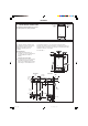
INSTALLATION BOILER ASSEMBLY - Exploded view INSTALLATION 7 24 30 27 35 Data Plate Condensate siphon trap 17 23 12 9 19 cla7926 26 37 LEGEND 9. Sightglass 23. PCB25E 30. Fan 12. Main Burner 24. Air pressure switch 35. Front Panel 17. Gas Valve 26. Controls Casing 37. Controls Door 19. Control Box 27. Flue Protection Thermostat 13 classic HE - Installation & Servicing 201850-6.
INSTALLATION INSTALLATION 8 UNPACKING The boiler is supplied fully assembled in Pack A, together with a standard flue assembly for lengths from 75mm (3") up to 705mm (27 3/4") rear flue and from 270mm (10 5/8") up to 775mm (30 1/2") side flue in Pack B. Pack A Contents Note. For side flue applications the optional extra side outlet kit is required.
INSTALLATION PACKAGING AND CASING REMOVAL INSTALLATION 9 1. Cut straps and remove outer carton. (a) Casing retaining screws 2. Remove packing from top of boiler (Note the wall mounting plate is packed on this packing) Front panel 3. Leave bottom packing in place. 4. Slightly open plastic controls door to gain access to the front panel fixing screws. 5. Remove the front casing as follows and place to one side to avoid damage. a.
INSTALLATION 11 FLUE ASSEMBLY - Exploded View 1 1. An optional flue duct extension kit is required for wall thicknesses greater than 775mm (30 1/2") side flue. Refer to Frame 10. 2 3 LEGEND 4 1. Terminal 5 6 2. Weather seal (optional extra) 3. Flue assembly 4. Boiler sealing ring 5. Flue extension pipe 6. 'O' ring REAR FLUE OUTLET 12 WALL MOUNTING TEMPLATE Note. The template shows the positions of the fixing holes and the rear flue outlet hole centre for standard installation.
INSTALLATION 14 CUTTING THE FLUE - wall thicknesses of 75 to 705mm Note. If the downward piping kit bracket is to be used, it is essential that 30mm is added to the measured wall thickness when marking the flue. 1. Measure and note the wall thickness X (Refer to Frame 10). 2. Mark the wall thickness onto the flue. 3. To ensure the tube is cut square, mark the flue all the way around. cla7841 4. Position the inner flue spring to support the inner flue during the cutting process. 5.
INSTALLATION 16 FITTING THE FLUE ASSEMBLY AND OPTIONAL FLUE FINISHING KIT (if required) (A) Without Optional Flue finishing Kit (B) With Optional Flue finishing Kit 1. Insert the flue assembly through the hole. 1. Fit the black outer wall seal over terminal and ensure the retaining rim is located in the terminal depression. 2. Ensure the notch is at the top. This will aid the location of the studs into the boiler back panel. A B 4 2 2. Fit flue pipe assembly through the hole previously cut in wall.
20 FLUE ASSEMBLY - Exploded view For wall thickness 270mm to 775mm 3 The optional side outlet kit is required for all side flue applications. 5 2 cla7712 An optional flue duct extension kit is required for lengths (distance from the outside wall to the relevant side of the boiler casing) greater than 775mm (30 1/2"). Refer to Frame 10. 1 4 LEGEND 1. 2. 3. 4. 5.
23 CUTTING THE FLUE - For flue lengths 270 to 775mm ONLY 1. Measure and note the side flue length "Y" (refer to Frame 10). 2. Add 143mm (55/8") to dimension "Y" and measuring from the ring, cut both outer and inner tube. Ensure support clip is in position to facilitate cutting. 3. To ensure the tube is cut square, mark the flue all the way around. 4. Cut to length and remove any burrs.
26 MOUNTING THE BOILER Note. The boiler may require two men to lift it onto the wall mounting plate. For downward routing of pipes the M5 spacer (supplied in 44 the downward piping kit) should now be fitted to the 78 cla back of the boiler. 1. The boiler is supplied for rear outlet installation. Remove the blanking plate from the top outlet and retain. 2. Remove the fan electrical connections, the air pressure switch sensing pipe, the CO/CO2 sensing pipe and the 2 fan fixing screws and 6 remove the fan.
SIDE FLUE OUTLET INSTALLATION 28 FLUE EXTENSION DUCTS - For flue lengths greater than 705mm rear flue or 775mm side flue Extension duct & clamp 1.0m (39") long Washers - 2 off Wall plugs - 2 off Flue duct support mxhe7656 Clamp screws - 2 off Support fixing screws - 2 off 29 FLUE EXTENSION DUCTS - continued Flue length R or L Accessories Product No.
INSTALLATION 31 FITTING THE OPTIONAL ROOF FLUE KIT (Flat or Pitched) Note. A flat or pitched roof flashing plate (not supplied) is required before proceeding with the installation of this kit. This kit is suitable for both flat and pitched roof terminations, using a concentric flue to run vertically from the top of the boiler and terminating above roof level. Connection to the top of the boiler is made using a separately supplied vertical connector kit.
INSTALLATION 33 FLUE TERMINAL POSITION The terminal should be positioned so that products of combustion can safely disperse at all times. Pluming may occur at the termination so, where possible, terminal positions where this could cause a nuisance should be avoided. Minimum dimensions are shown below ex7532 610 mm min. Terminal Position Minimum Dimension Directly below an opening, air brick, windows, etc.
INSTALLATION 35 ASSEMBLING THE ROOF FLUE KIT Determine the correct height that the flue should terminate above the roof. If after calculating or measuring the overall flue height from the top of the boiler, it is necessary to cut both pipes of assembly A, then ensure they are cut equally leaving the inner flue tube longer than the outer air tube as supplied. (Refer to No. 7 below) Ensure the cut pipe ends are free from any burrs. 1. Ensure the flue seal collar B is located onto the flue assembly A.
INSTALLATION INSTALLATION 36 GAS CONNECTION 37 WATER CONNECTIONS Refer to 'Gas Supply ', page 8. 1. Remove the plastic plugs from the flow and return pipes. Refer to Frame 2 for gas inlet service dimensions. A minimum pressure of 20 mbar MUST be available at the boiler inlet with the boiler operating. The main gas cock is on the left hand side of the gas control valve, as shown. To facilitate connection the gas cock may be removed from the gas control valve. 2.
INSTALLATION INSTALLATION 40 CONDENSATE PIPE TERMINATION CONFIGURATIONS . . . continued 3. INTERNAL CONNECTION TO SOIL AND VENT STACK Termination into a down pipe can take place providing it can be confirmed that the down pipe is part of a combined waste and rain water system. BOILER * Make connection to SVP using a solvent welded saddle. Air Break cla9253 4. TERMINATION TO SOAK AWAY External wall Termination to Soak away BOILER cla7774 minimum 500mm Ground Level 5.
41 ELECTRICAL CONNECTIONS WARNING. The appliance must be efficiently earthed. A mains supply of 230 V ~ 50 Hz is required. All external controls and wiring must be suitable for mains voltage. Wiring should be in 3-core PVC insulated & sheathed cable, not less than 0.75mm2 (24 x 0.2mm) to BS. 6500 Table 16 Wiring Regulations and local regulations. For IE reference should be made to the current ETCI rules for electrical installations.
43 PICTORIAL WIRING Flue protection thermostat LEGEND b - blue bk - black br - brown gy - grey or - orange pk - pink r - red v - violet w - white y - yellow y/g - yellow/green INSTALLATION INSTALLATION Limit thermostat Thermostat sensor cla7677 44 MID POSITION VALVE Pumped only Notes. 1. Some earth wires are omitted for clarity. Ensure proper earth continuity when wiring. 2. Numbering of terminals on thermostats is specific to the manufacturer. 3.
INSTALLATION INSTALLATION 45 TWO SPRING CLOSED VALVE Pumped only Notes. 1. Some earth wires are omitted for clarity. Ensure proper earth continuity when wiring. 2. Numbering of terminals on thermostats is specific to the manufacturer. 3. This is a fully controlled system - set the boiler thermostat to maximum. 4. Switchmaster valve has grey and orange auxiliary switch leads but the grey wire must be connected to the live supply.
INSTALLATION INSTALLATION 47 COMMISSIONING AND TESTING The Benchmark Log Section of this book or equivalent self certification should be completed and signed to demonstrate compliance with Building Regulations. A. ELECTRICAL INSTALLATION B. GAS INSTALLATION 1. Checks to ensure electrical safety should be carried out by a competent person. 2. ALWAYS carry out preliminary electrical system checks, i.e. earth continuity, polarity, resistance to earth and short circuit using a suitable test meter. 1.
49 INITIAL LIGHTING - continued 19. Swing the control box back into its working position and secure. 20. Refit the controls pod to the boiler casing and tighten the 2 front fixing screws. cla7679 21. Close the pod door. cla7678 INSTALLATION INSTALLATION controls support fixing screws 50 GENERAL CHECKS Make the following checks for correct operation: Knob Setting 1. Set the boiler thermostat knob to position 6 and operate the mains on/off switch.
SERVICING 52 SERVICING SCHEDULE 5. Clean the main and pilot injectors. Refer to Frame 56. To ensure the continued safe and efficient operation of the appliance it is recommended that it is checked at regular intervals and serviced as necessary. The frequency of servicing will depend upon the installation condition and usage, but should be carried out at least annually. It is the law that any service work must be carried out by CORGI registered installer.
SERVICING 55 CLEANING THE FAN ASSEMBLY / THE FLUEWAYS 1. Remove the air pressure switch and CO/CO2 sensing pipes. 2. Disconnect the electrical connections. 3. Remove the 2 fan fixing screws and remove the fan by pulling forward. 2 1 4. Pull off the two electrical connections to the flue protection thermostat. 4 5. Slacken the two M5 nuts on the front tie rods, releasing the tie rods from the combustion chamber. 6. Unhook the rear collector hood tags and remove collector hood. 7. Remove the flue baffles.
SERVICING 4 58 CLEANING THE SIPHON 1. Pull the heat shield forward 1 to remove from clips. 2. Unscrew the siphon union connection. 3. Remove the rubber sump connection pipe and the blockage sensing pipe. 4. Remove the two siphon retaining screws and remove siphon. 5. Thoroughly clean the siphon. 6. Recharge the siphon with water. 7. Re-assemble in reverse order. Ensuring the rubber sump connection pipe and blockage sensing pipe are correctly replaced. 3 2 Reassemble the boiler in the following order. 1.
SERVICING 63 OVERHEAT THERMOSTAT REPLACEMENT 4. Pull off the electrical connections at the thermostat. Remove the backnut retaining the thermostat to the casing. Withdraw the thermostat phial from the heat exchanger pocket and unclip from the casing. 1. Refer to Frame 61. 2. Remove the control box fixing screws. 3. Swing the control box down into the servicing position. 5. Fit the new thermostat and reassemble in reverse order. 6. Check the operation of the boiler.
SERVICING 65 LIMIT THERMOSTAT REPLACEMENT Return pipe Flow pipe 1. Refer to Frame 61. 2. Remove the limit thermostat assembly from the boiler flow pipe. 2 3 3. Disconnect the electrical connectors 4. Clip new thermostat onto flow pipe 5. Reassemble in reverse order. NOTE. UNDER NO CIRCUMSTANCES REFIT THE LIMIT THERMOSTAT ONTO THE RETURN PIPE 66 FLUE PROTECTION THERMOSTAT REPLACEMENT 1. Refer to Frame 61. SERVICING 2 2. Pull off the two electrical connections. 3.
SERVICING 68 IGNITION ELECTRODE AND LEAD REPLACEMENT 1. Refer to Frame 61. 2. Remove the burner and air box assembly. Refer to Frame 54. 3. Remove the electrode retaining nut. 4. Remove the pilot shield. 5. Remove the ignition electrode and integral lead. 6. Refit the new electrode and lead in reverse order. Ensure that the pilot shield is replaced. 7. Check the spark gap. Refer to Frame 67. 8. Reassemble in reverse order. 9. Check the operation of the boiler.
SERVICING Air pressure switch & CO/CO2 sensing pipes 71 FAN REPLACEMENT Electrical connections 1. Refer to Frame 61. 2. Remove the two fan electrical connections, the red pressure sensing pipe, the blue CO/CO2 sensing pipe and the two fan fixing screws. 3. Pull the fan forward, remove and retain. 4. Fit the new fan and reassemble in reverse order, ensuring the fan leads, 2 sensing tubes and the two fan fixing screws are reconnected. 5. Check the operation of the boiler.
SERVICING 75 HEAT EXCHANGER REPLACEMENT Note. Refer to Frame 7 (Boiler assembly - Exploded view) for illustration of the procedure detailed below. 1. Refer to Frame 61. 2. Remove the burner / air box assembly. Refer to Frame 54. 3. Drain the system. 12. Remove the 2 rubber sealing grommets from the top of the back panel to facilitate fitting the new assembly. 13. Fit the new heat exchanger assembly, complete with water pipes, and hang it on the bottom key hole slots and screws.
SERVICING 77 SIPHON REPLACEMENT 3 1. Refer to Frame 61. 2. Remove the burner. Refer to Frame 54. 3. Pull the heat shield forward to remove from clips. 4. Pull off the rubber sump connecting pipe and the blockage sensing pipe. 5. Unscrew the connection. siphon union 6. Remove the two siphon retaining screws and remove siphon. 7. Re-fit the new siphon and gasket and reassemble in reverse order, ensuring the rubber sump connecting pipe and blockage sensing pipe are correctly replaced. 6 4 SERVICING 8.
FAULT FINDING START Is the mains on neon 'I3' illuminated? NO FAULT FINDING FAULT FINDING FAULT FINDING YES Is there a live supply on EITHER NO terminal of overheat 'stat? Check mains supply and fuses. Check programmer and system thermostats are all ON. Check that boiler plug and socket are OK and fully connected.
SHORT LIST OF PARTS The following are parts commonly required due to damage or expendability. Their failure or absence is likely to affect safety or performance of this appliance. The list is extracted from the British Gas List of Parts, which contains all available spare parts. The full list is held by British Gas, Ideal Stelrad Group distributors and merchants. When ordering spares please quote: 1. 2. 3. 4. 5. Boiler Model Appliance G.C.
SHORT LIST OF PARTS 78 SHORT PARTS LIST 9 12 14 13 13 A 15 18 19 17 23 24 26 FUSE 27 30 35 37 39 45 59 cla7850 classic HE - Installation & Servicing 44 201850-6.
INSTALLER NOTIFICATION GUIDELINES IT IS A REQUIREMENT OF CORGI MEMBERSHIP TO REGISTER EVERY GAS APPLIANCE In addition a change to Building Regulations (England and Wales) requires the installer to notify when installing a heating appliance, as from 1st April 2005.
BENCHMARK No. GAS BOILER COMMISSIONING CHECKLIST COLLECTIVE MARK BOILER SERIAL No. NOTIFICATION No.
SERVICE INTERVAL RECORD It is recommended that your heating system is serviced regularly and that you complete the appropriate Service Interval Record Below. Service Provider. Before completing the appropriate Service Interval Record below, please ensure you have carried out the service as described in the boiler manufacturer's instructions. Always use the manufacturer's specified spare part when replacing all controls SERVICE 1 DATE SERVICE 2 DATE ENGINEER NAME COMPANY NAME TEL No.
Technical Training The Ideal Boilers Technical Training Centre offers a series of first class training courses for domestic, commercial and industrial heating installers, engineers and system specifiers. For details of courses please ring: ............ 01482 498 432 The code of practice for the installation, commissioning & servicing of central heating systems CERTIFIED PRODUCT Manufactured under a BS EN ISO 9001: 2000 Quality System accepted by BSI Ideal Boilers, P.O.
users guide classic Your Ideal users guide See reverse for classic installation & servicing instructions HE9, HE12, HE15, HE18 When replacing any part on this appliance use only spare parts that you can be assured conform to the safety and performance specification that we require. Do not use reconditioned or copy parts that have not been clearly authorised by Ideal Boilers. 201850-6.
classic HE (Natural Gas Only) Destination Countries: GB, IE INTRODUCTION HE9 HE12 HE15 HE18 SAFETY Current Gas Safety (Installation & Use) Regulations or rules in force. In your own interest, and that of safety, it is the law that this boiler must be installed by a CORGI registered installer. In IE the installation must be carried out by a competent person and installed in accordance with the current edition of I.S.
CONTROL OF WATER TEMPERATURE BOILER OVERHEAT THERMOSTAT 1. Adjust the boiler thermostat (B) to give the required temperature of central heating. The boiler is fitted with a safety 'cutout' thermostat. This will shut down the boiler in the event of overheating. Should this occur allow the boiler to cool, press the reset button (E) then relight as detailed in steps 1-8 in 'To light the boiler'. 2. The boiler thermostat automatically switches the main burner OFF and ON to maintain the selected temperature.
POINTS FOR THE BOILER USER Note. In line with our current warranty policy we would ask that you check through the following guide to identify any problems external to the boiler prior to requesting a service engineers visit. Should the problem be found to be other than with the appliance we reserve the right to levy a charge for the visit, or for any pre-arranged visit where access is not gained by the engineer.