INSTALLATION & SERVICING Concord CXSi 110/H-180/H BOILERS 157294-3.
GENERAL Concord CXSi/H - Installation & Servicing 2 157294-3.
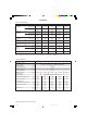
GENERAL Table 1 - Performance Data Boiler CXSi 110/H Boiler Input Gross kW Low Rate Btu/h x 1000 Nett Boiler Input kW CXSi 140/H CXSi 160/H 119.5 136.6 CXSi 180/H 93.9 102.5 153.7 320.5 349.6 407.9 466.1 524.4 84.6 92.3 107.7 123.1 138.5 Btu/h x 1000 288.7 315.0 367.4 419.9 472.4 kW 134.2 146.4 170.8 195.2 219.6 Btu/h x 1000 457.8 499.4 582.7 665.9 749.1 kW 120.9 131.9 153.8 175.8 197.8 Btu/h x 1000 412.4 449.9 524.9 599.9 674.
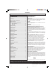
GENERAL Concord CXSi 110/H-180/H (Natural gas) B.G. Certified - P.I. No. 87/AQ/341 CONTENTS Air Supply. ........................................................................ 9 Boiler Assembly - exploded view. ............................... 10 Boiler Clearances. ........................................................... 6 Burner Assemblies - exploded views. ............................ CXSi 110/H-160/H. ................................................. 25 CXSi 180/H. ..................................
GENERAL FROST PROTECTION WATER CIRCULATION SYSTEM Frost protection is incorporated in the boiler as long as there is a permanent Live supply wired to Terminal L1 on the terminal plug-in connection at the control box and the boiler thermostat knob is not switched to Off. If the temperature sensed by the boiler thermostat falls to about 50C the boiler will fire until the temperature reaches 180C. Note that this is designed to protect the boiler and may not necessarily protect remote parts of the system.
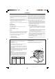
GENERAL H 2 C CXS XSi 14 i 12 0/H 0/H CXSi 180/H Con 1900 Si 1 10/ Con 1898 CX CXSi 160/H CXSi 110/H CXSi 120/H CX CXS Si 180 i 16 /H 0/H CXSi 140/H Graph 2 - Hydraulic Resistance Graph 1 - Heat Load / Water Volume CLEARANCES & DIMENSIONS Table 3 Boiler Size CXSi 110/H CXSi 120/H CXSi 140/H CXSi 160/H CXSi 180/H Front clearance mm (in) 700 (27 1/2) Rear clearance mm (in) 200 (8) Side clearance mm (in) 100 (4) - not including clearance for side fitted flow header Dimension A m
GENERAL PUMP POSITIONS Whenever practically possible the circulating pump(s) should be positioned so that it pressurises the system being served. The vertical distance between the pump(s) and any cold feed and expansion cistern MUST comply with the pump manufacturers requirements, in order to avoid cavitation. These requirements override the information given in Frame 3 if the static head required for the pump(s) exceeds that required for the boiler.
GENERAL evaporate a large portion of the system water capacity over a full heating season. There will always be corrosion within a heating or hot water system to a greater or lesser degree, irrespective of water characteristics, unless the initial fill water from the mains is treated. Even the water in closed systems will promote corrosion unless treated.
GENERAL FOUNDATION CHIMNEY SYSTEM The boiler must stand on a non-combustible floor (i.e. concrete or brick) which must be flat, level and of a suitable load bearing capacity to support the weight of the boiler (when filled with water) and any ancillary equipment.
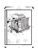
INSTALLATION INSTALLATION 5 CONCORD CXSi BOILER ASSEMBLY - Exploded view Insulation not shown Legend 1. Cleanout cover 8. Distribution tube. 15. Lightback shield. 2. Collector hood 9. Downdraught deflector. 16. Burner manifold assy. 3. Middle section 10. Section bolt. 17. NOx duct. 4. Flow header 11. Drain cock. 18. Insulation bracket 5. Section alignment rings & 'O' rings. 12. Base plate. 6. Thermostat pocket. 13. Combustion chamber. 7. End section. 14. Tie rods.
6 BOILER SECTION ASSEMBLY The site assembled boiler is supplied in the following packages: TOOLS REQUIRED ! Spanners ! Combustion chamber / manifold / burner assembly. ! Torque wrench ! Platework package. ! Pozi screwdriver ! Casing package. ! Mallet ! Controls box package. ! End and centre sections. GENERAL The installation of the boiler must be in accordance with current Gas Safety (Installation and Use) Regulations or rules in force, building regulations, I.E.E. (BS.
INSTALLATION INSTALLATION 7 BOILER SECTION ASSEMBLY - continued Side elev. of d/deflector-insulation assy. 12. Offer the downdraught deflector to the projecting studs at the back of the combustion chamber and fix, using the nuts and washers provided. 13. Fit the insulation brackets with the screws provided to the downdraught deflector. 14. Refit the burner assembly to the combustion chamber and tighten the 4 nuts securing the burner manifold to the combustion chamber legs.
INSTALLATION BOILER ASSEMBLY 1. Fit the distributor tube into the selected return connection. Ensure that the tube flange aligns horizontally and that the 2 sealing gaskets are correctly assembled on the tube refer to alignment notches. INSTALLATION 8 5. Complete the system connections (using suitable jointing compound) as follows: The cast iron flow header must be fitted in the chosen flow connection which will be either of the 2 top rear tappings.
INSTALLATION INSTALLATION 11 CASING ASSEMBLY 4 3 Legend 2 1. Side panel. 2. Supporting angle. 5 3. Top panel. 1 4. Upper front panel. 5. Control box. 6 6. Bracket. 7 7. Support frame. 8 8. Door panel. 9. Lower panel. 9 Co n1 46 6 1. Fit the support angle to the collector hood and fasten, using the M5 screws and washers. 2. Fit the front fixing bracket(s) to the collector hood and fasten, using the M5 screws and washers through the slotted holes. 3.
INSTALLATION 1. Make the 3 electrical connections from the overheat thermostat (fixed to the upper front framework) to the terminals marked 'Limit Stat' on the electrical plug-in connector from the gas valve plug lead assembly, as follows: C Pink N/O Red INSTALLATION 12 CONTROL BOX C N/O N/C N/C White 2. Unpack the control box. Fit the plug-in connector from the gas valve plug lead assembly to the bottom box at the back of the control box and fasten, using the M4 screws and washer.
13 CONTROL BOX - continued 7. Run the flame detector lead through the clips on the front of the combustion chamber base tray and plug it into the flame detector electrode on the LH end burner. Ensure that any slack is tucked neatly into the clips then fasten the clips. NOx duct Con 1915 INSTALLATION INSTALLATION 8.
INSTALLATION To gain access to the inside of the control box remove The boiler can be controlled either by volt-free external contacts the 2 M4 screws, lift up the plastic front panel and lower. connected between terminals X1 and X2 or by a switched This should serve only the boiler, together with its controls and pumps.
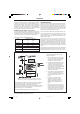
RED Y/G RED N B HD B L5 L3 250 250 B L4 N/C N/O C N N N N N GV2 HIGH YELLOW VIOLET RED BLUE N VOLT-FREE BOARD (OPTION) missing pin on board blanking pin in female half O/H L/O L/O O/H ON ON CONTACT REMOVED AND FITTED TO MATING HALF BOILER ON OVERHEAT VOLT FREE CONTACTS LOCKOUT 2 X VIOLET L/O HL2 R HL1 GV BK B BR B RESET BR ORANGE Note: Diagrammatic only - physical positions not shown PL B ON BR 2 WHITE ORANGE GV1 LOW 2 X RED S4561B1047 BR L/O 3 VIOLET SPARK GEN
INSTALLATION INSTALLATION 16 ZONES WITH BI-DIRECTIONAL MOTORISED VALVES IMPORTANT Terminal L2 may control the appropriate pump(s) directly, provided that the total running or starting current does not exceed 6A (resistive or inductive): if this rating would be exceeded, then appropriate switchgear must be used to control the pumps indirectly. Three zones are illustrated but the principles may be extended as required, provided the above conditions are met.
INSTALLATION INSTALLATION 18 ZONES WITH SPRING-RETURN MOTORISED VALVES IMPORTANT Terminal L2 may control the appropriate pump(s) directly, provided that the total running or starting current does not exceed 6A (resistive or inductive): if this rating would be exceeded then appropriate switchgear must be used to control the pumps indirectly. X2 Three zones are illustrated but the principles may be extended as required, provided the above conditions are met.
INSTALLATION 1. Check that the boiler thermostat knob (1) on the control box (2) is OFF. INSTALLATION 20 INITIAL LIGHTING 7. The boiler will light at Low rate and the Boiler-on light (5) will be illuminated. If it does not light the Lockout light (6) will be illuminated. Press in and release the Lockout button (7). The controls will reset and attempt to relight. 2. Ensure that the mains gas inlet cock (3) is open (groove in the square head in line with the gas pipe). 8.
INSTALLATION INSTALLATION 21 MANIFOLD GAS PRESSURE - CXSi 110/H-160/H ONLY The manifold setting pressure must now be checked and adjusted as necessary. It is essential to set the High Pressure first Start the adjustment procedure with the system cold, on full load and with all temperature controls set to maximum to avoid thermostatic shutdown. Remove the screw in the burner setting pressure test point and connect a suitable gas pressure gauge.
INSTALLATION The manifold setting pressure must now be checked and adjusted as necessary. It is essential to set the High Pressure first INSTALLATION 22 MANIFOLD GAS PRESSURE - CXSi 180/H ONLY Inlet PTP Start the adjustment procedure with the system cold, on full load and with all temperature controls set to maximum to avoid thermostatic shutdown. Remove the screw in the burner setting pressure test point and connect a suitable gas pressure gauge.
INSTALLATION SERVICING 23 SPILLAGE CHECK Check that there is no spillage of combustion products from the boiler draught diverter by carrying out a spillage test, as detailed in BS. 5440:1. 24 TESTING Check the main burner responds correctly to manual on/off operations of any controls fitted in the gas control circuit. Check the operation of the flame failure safety system by lighting the boiler and then turning the gas inlet cock off.
SERVICING 27 SERVICING Caradon Ideal Limited does not accept any liability resulting from the use of unauthorised parts or the repair and servicing of appliances not carried out in accordance with the Company’s recommendations and specifications. A comprehensive service should be carried out at least once a year. The User is advised to make a contract with a CORGI registered installer. WARNING.
SERVICING 28 REPLACEMENT OF COMPONENTS - Refer to Frames 5, 31 and 32 GENERAL WARNING. ALWAYS turn OFF the gas supply at the gas inlet cock and switch OFF and DISCONNECT the electricity supply BEFORE working on the appliance. 29 GAS CONTROL VALVE 30 MAIN BURNER 1. Undo and pull off all the plugs from the gas valve solenoids. 2. Turn off the gas at the gas inlet cock. Undo the 2 unions at either side of the gas valve assembly and remove the assembly (complete) to a suitable working area. 3.
SERVICING 32 BURNER AND CONTROLS ASSEMBLY - Exploded view - CXSi 180/H LEGEND 10. Main burner (RH). 2. Gas inlet union. 3. 'O' ring seal. 4. High/low gas control valve. 7. Burner manifold. 11. Ignition electrodes. 5. Gas control valve. 8. Main injector. 12. Detection electrode assembly. 6. Spark generator. 9. Main burner - LH. PTP Pressure test point. SERVICING 1. Main gas inlet cock. 33 OVERHEAT THERMOSTAT 1.
SERVICING 34 CONTROL BOX - Basic Boiler, Exploded View 1 Printed circuit board support detail 2 12 3 5 6 7 2 1 SERVICING 4 8 10 Con 1911 11 9 LEGEND 1. Wiring clamp. 5. Terminal strip 9. 2. Connection box plug. 6. Back panel 10. Warning light lens 3. Connection box. 7. Lockout reset button 11. Controls box 4. PCB S456B1047 8. Thermostat knob 12. PCB W 4115A1020 Potentiometer 35 CONTROL SENSOR 1. Lift off the casing top panel and front panel. 2.
SERVICING 36 CONTROL SENSOR POTENTIOMETER ASSEMBLY PCB 1. Prise the front cap from the thermostat knob. Plug 2. Carefully loosen the brass retaining nut one full turn anticlockwise 3. Gently pull the thermostat knob from the potentiometer. When reassembling ensure the arrow on the body is lined up in the OFF position. Backnut 4. Remove the back nut and brass washer securing the thermostat knob to the panel. Potentiometer 5. Undo and remove the 2 screws securing the control box front panel.
FAULT FINDING FAULT FINDING FAULT FINDING FAULT FINDING FAULT FINDING FAULT FINDING FAULT FINDING 40 BOILER CONTROL Before attempting any electrical fault finding ALWAYS carry out the preliminary electrical system checks as detailed in the Instructions for the British Gas Multimeter or other similar commercially available meter. The preliminary electrical system checks are the FIRST electrical checks to be carried out during a fault finding procedure.
Before carrying out any Fault Finding, ensure that all internal controls are calling for heat and that the overheat thermostat has not operated. There should be 230V ± 10% available at the control box connection.
SHORT LIST OF PARTS The following are parts commonly required as replacements, due to damage or expendability. When ordering spare parts please quote: 1. Boiler model 2. Boiler serial no. (refer to the data plate on the combustion chamber) 3. Boiler P.I. No. (refer to the data plate on the combustion chamber) Their failure or absence is likely to affect the safety and/or performance of this appliance. 4. Description 5. Quantity 6. Product no.
SHORT LIST OF PARTS Key No. Description Qty. Product No. 45 Control box complete 1 155 641 46 Thermistor 1 154 816 47.1 PCB S4561B1047 (ignition) 1 154 814 48.1 PCB W4115A1020 (Aquastat) 1 154 815 56 Casing assembly complete .................................................. CXSi 110/H & 120/H 1 157 449 56 Casing assembly complete ................................................................ CXSi 140/H 1 157 450 56 Casing assembly complete ...................................
NOTES Concord CXSi/H - Installation & Servicing 34 157294-3.
NOTES Concord CXSi/H - Installation & Servicing 157294-3.
Technical Training The Ideal Boilers Technical Training Centre offers a series of first class training courses for domestic, commercial and industrial heating installers, engineers and system specifiers. For details of courses please ring: .......... 01482 498 432 Ideal Boilers, P.O. Box 103, National Ave, Kingston upon Hull, HU5 4JN. Telephone: 01482 492 251 Fax: 01482 448 858. Registration No. London 322 137.