IDEAL INDUSTRIES, INC. TECHNICAL MANUAL MODEL: 61-310 This Service Manual provides the following information: ● Precautions and safety information ● Specifications ● Basic maintenance (cleaning, replacing the battery and fuses) ● Performance test procedures ● Calibration and calibration adjustment procedures Form Number: TM61310 Revision: 2.
TABLE OF CONTENTS Page Introduction 1 Precautions and Safety Information 1 Symbols 1 Safety 2 Specifications 3 General Specifications 3 Measurement Characteristics 4 Voltage Specifications 4 Current Specifications 4 Resistance Specifications 5 Diode Check, Continuity, Temperature Specifications 5 Auto Power Off, Data Hold Function, Battery Test 5 Physical and Environmental Characteristics 6 Certifications and Compliances 6 Required Equipment 7 Basic Maintenance 8 Opening th
Page 1 Introduction Warning To avoid shock or injury, do not perform the verification tests or calibration procedures described in the manual unless you are qualified to do so. The information provided in this document is for the use of qualified personnel only. Caution The 61-310 series contain parts that can be damaged by static discharge. Follow the standard practices for handling static sensitive devices. For additional information about IDEAL INDUSTRIES, INC.
Page 2 SAFETY Review the following safety precautions to avoid injury and prevent damage to this product or any products connected to it. To avoid potential hazards, use the product only as specified. For operating instructions, see the 61-310 Digital Multimeter Instruction Manual. CAUTION: These statements identify conditions or practices that could result in damage to the equipment or other property.
Page 3 SPECIFICATIONS All specifications are warranted unless noted typical and apply to the 61-310. Stated accuracies are at 23°C±5°C at less than 70% relative humidity and without the battery indicator displayed.
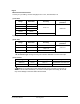
Page 4 Measurement Characteristics Accuracy is ±(% reading + number of digits) at 23°C ± 5°C, less than 80% R.H. (1) DC Volts Range Resolution Accuracy 200.0mV 100μV 2.000V 1mV 20.00V 10mV 200.0V 100mV 600V 1V 0.8% + 2 Resolution Accuracy 0.5% + 2 Over voltage protection 600V rms Input Impedance: 10MΩ (2) AC Volts Range Over voltage protection 40-400Hz 200.0V 100mV 1.2% + 10 600V 1V 1.2% + 10 600V rms Input Impedance: 4.
Page 5 (4) Resistance Range Resolution Accuracy 200.0Ω *1 0.1Ω 0.8% + 4 2.000KΩ 1Ω 20.00KΩ 10Ω 200.0KΩ 100Ω 2.000MΩ 20.00MΩ * Over voltage protection 250V rms 0.8% + 2 1KΩ 2 10KΩ 3.0% + 3 Open circuit Voltage: -1.5V approx. *1 < 5 digit of reading rolling. *2 ± 2% of reading rolling. (5) Diode Check and Continuity Range Resolution Accuracy Max. Test Current Max. Open Circuit Voltage 1mV Not specified * 1mA, approx. 2.8V, approx.
Page 6 Physical and Environmental Characteristics Characteristics Description Dimensions (H×W×D) 150mm(H) ×76mm (W) ×38mm(D) (with holster) 5.9” (H) x 3.0”(W) x1.5”(D) Weight (with battery& holster) 0.219Kg (7.1 oz.) Environmental characteristics Description Temperature operating range 0 to +40°C Non-Operating -20 to +60°C <80% R.H. Humidity (operating) <75% R.H. Altitude 6561.7 Ft.
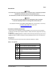
Page 7 Required Equipment Required equipment is listed in Table B. If the recommended models are not available, equipment with equivalent specifications may be used. Repairs or servicing should be performed only by qualified personnel. Table B. Required Equipment Equipment Calibrator Required Characteristics AC Voltage Range: 0 ~ 750V AC Accuracy: ±0.07% (Basic) Frequency Range: 40 ~ 1KHz Accuracy: ±2% DC Voltage Range: 0 ~ 1000V DC Accuracy: ±0.
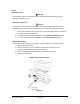
Page 8 Basic Maintenance Warning To avoid shock, remove the test leads and any input signals before opening the case or replacing the battery or fuses. Opening the Meter Case Caution To avoid an unintentional short circuit, always place the uncovered meter assembly on a protective surface. When the case of the meter is open, circuit connections are exposed. 1. Disconnect test leads from any live source, turn the rotary switch to OFF, and remove the test leads from front terminals. 2.
Page 9 Replacing Fuses Warning To avoid electrical shock, remove the test leads and any input signals before replacing the battery or fuses. To prevent damage or injury, INSTALL ONLY quick acting fuses with the following Amp/Volt current interrupt rating: F-310 Fuse: 250mA 250V FAST BLOW Fuse Fuse Replacement The 61-310 replacement fuse is part number: F-310 Fuse Rating is: 250mA 250V FAST BLOW 1. Remove the rubber holster. 2. Remove the two screws on the battery cover and open the battery cover. 3.
Page 10 Performance Tests The following performance tests verify the complete operability of the meter and check the accuracy of each meter function against the meter’s specifications. Accuracy specifications are valid for a period of one year after calibration, when measured at an operating temperature of 18°C to 28°C and a maximum of 80% relative humidity.
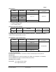
Page 11 Table 2: AC Voltage Test: Step Range Input Frequency Reading 1 200V 2.0V 60Hz 1.0 to 3.0 2 200V 2.0V 400Hz 1.0 to 3.0 3 200V 190.0V 60Hz 186.7 to 193.3 4 200V 190.0V 400Hz 186.7 to 193.3 5 600V 600V 60Hz 583.0 to 617.0 6 600V 600V 400Hz 583.0 to 617.0 Testing the DC milliamps and DC amps Function 1. Turn the rotary switch to the DCA function and range shown in Table 3. 2. Apply the inputs for steps 1-3 in Table 3. 3.
Page 12 Table 4: Ω Resistance Test: Step Range 1 *200 OHM 2.0Ω 2 *200 OHM 190.0Ω 188.3 to 191.7 3 2K OHM 1.900KΩ 1.883 to 1.917 4 20K OHM 19.00KΩ 18.83 to 19.17 5 200K OHM 190.0KΩ 188.3 to 191.7 7 20M OHM 19.00MΩ 18.40 to 19.60 Source Reading 1.6 to 2.4 *Lead resistance on the 200 ohm range is not included in error. Checking the Diode Test Function To check the diode test function, do the following: 1. Connect the calibrator to the VΩ and COM inputs on the meter. 2.
Page 13 Calibration Procedure To Recalibrate your meter: It is recommended that the Multimeter be calibrated once each year. 1. Perform calibration at an ambient temperature of 23°C±2°C and a relative humidity of <70% Disconnect the test leads and turn the meter off. Remove the test leads from the front terminals. 2. Position the meter face down. Remove the battery cover screws and the 2 bottom case cover screws. 3.