
User's Manual

Product Manual
ESC1000 – Downlight/LED Smart Connector
ND 8202-1 11/2015 Users Manual – ESC1000 Emerge Downlight/LED Smart Connector Page 2
www.idealindustries.com
IDEAL Model ESC1000 LED Smart Connector Installation Instructions
WARNING: This is a current rated device. Use in applications involving
Amperage beyond its rating can be dangerous and cause electrical fires.
Wiring must comply with all applicable electrical codes.
Turn off power before removing or installing connector.
TERMINOLOGY
24V Input: Incoming power feed from 24V source (DC Flex-Zone)
LOAD: Power output from Smart Connector to 24V DC LED Fixture input
DIM: 0-10 VDC dimming control output from Smart Connector to LED Fixture
dimming input
CONNECTING THE WIRES
Power
The 24V Input Connector accepts 12 AWG-18 AWG copper conductors, solid or stranded
(19 strands or less for 12 AWG-16 AWG, 7 strands or less for 18 AWG).
Use only one conductor per port and ensure that no copper is exposed on any of the
wires after installation.
1. Strip wires to 1/2”.
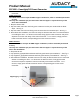
2. Grip +24V wire and firmly push conductor into one of the black LINE ports. See Fig. 2.
3. Grip -24V wire and firmly push conductor into one of the unmarked LINE ports. See Fig. 2.
4. For feed-through (i.e., “daisy-chain”) installations, insert the +24V feed-through conductor
into the other black line port. Insert the -24V feed-through conductor into the other
unmarked LINE port. See Fig. 2.
5. After 24V wire installation, the supply power can safely be disconnected and re-connected
without re-installing the wires. To disconnect the supply power, firmly grip the LINE
connector and pull to separate it from the main body of the Smart Connector. To re-
connect, simply push the LINE connector into the corresponding port on the Smart
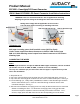
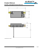
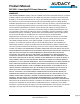
DIM Connector
Antenna
LINE Connector
LOAD
Connector
Fig. 1
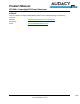
Fig. 2
LINE
Connector
LOAD
Connector
LINE neutral & feed-through
LINE hot & feed-through