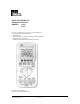
IDEAL INDUSTRIES INC. TECHNICAL MANUAL MODELS: 61-633 61-635 The Service Information provides the following information: • Precautions and safety information • Specifications • Basic maintenance (cleaning, replacing the battery and fuses) • Performance test procedures • Calibration and calibration adjustment procedures Form Number: TM61633-5 Revision: 5.
TABLE OF CONTENTS Title Introduction Precautions and Safety Information Symbols Page 1 1 1 Safety Information 2 Specifications 3 General Specification 3 Voltage Specifications 4 dBm / dB Specifications 4 Current Specifications 5 Peak Hold, Resistance Specifications 5 Continuity and Diode Specifications 5 Capacitance Specifications 6 Frequency Counter and Duty Factor Specifications 6 Temperature Specifications 6 Physical and environment characteristics 6 Certification and compliance
Page 1 Introduction Warning To avoid shock or injury, do not perform the verification tests or calibration procedures described in this manual unless you are qualified to do so. The information provided in this document is for the use of qualified personnel only. Caution The 61-630 serials contain parts that can be damaged by static discharge. Follow the standard practices for handling static sensitive devices.
Page 2 SAFETY Review the following safety precautions to avoid injury and prevent damage to this product or any products connected to it. To avoid potential hazards, use the product only as specified. CAUTION. These statements identify conditions or practices that could result in damage to the equipment or other property. WARNING. These statements identify conditions or practices that could result in personal injury or loss of life. Specific precautions Use proper Fuse.
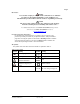
Page 3 SPECIFICATIONS All specifications are warranted unless noted typical and apply to models 61-633 and 61-635. Stated accuracies are at 23° ±5°C at less than 80% relative humidity and without the battery indicator displayed. General specifications Description 4¾ or 3¾ 80 Segment Graph 40,000 or 4,000 2 times / sec (40.
Page 4 Measurement Characteristics All at 23°C ±5°C, < 80% Rh. Specifications are expressed as ±([% of reading] + [number of digits]). Multiply accuracy Digits by l0 in 40,000 count Mode. DC VOLTAGE: DCV 40mV 400mV 4V, 40V, 400V, 1000V 61-633 ± (0.20%+8d) ± (0.20% + 2d) ± (0.20% + 2d) 61-635 ± (0.06% + 8d) ± (0.06% + 2d) ± (0.
Page 5 DC CURRENT: DCA 40mA, 400mA, 4A, 10A 61-633 ± (0.50% + 4d) 61-635 ±(0.20% + 4d) AC CURRENT: ACA 40mA, 400mA, 4A, 10A Bandwidth 61-633 ±(1.20% + 8d) 40Hz ~ 400Hz 61-635 ± (0.80% + 8d) 40Hz ~ 400Hz Range: 40mA, 400mA, 4A, 10A Resolution: 1µA in the 40mA range Burden Voltage: 800mV max. for mA input, 1V max.
Page 6 CAPACITANCE Capacitance 4nF, 40nF 400nF, 4µF 40µF, 400µF 4mF, 10mF 61-633 61-635 ± (1 .90% + 20d) ± (0.90% + 20d) ± (2.90% + 20d) ± (3.90% + 20d) ± (1 .90% + 20d) ± (2.90% + 20d) Note: For best measurements, use REL mode in the nF ranges. Range: 4nF, 40nF, 400nF, 4µF, 40µF, 400µF, 4mF, l0mF Resolution: lpF in the 4nF range Input Protection: 600V rms FREQUENCY COUNTER Range: 400Hz, 4KHz, 40KHz, 400KHz, 4MHz Resolution: 0.01Hz in the 400Hz range Accuracy: ± (0.01% + 1d) Sensitivity: 0.
Page 7 Certifications and compliances Safety Designed to IEC 1010-1, UL3111-1 and CSA specifications 1000V DC Category II Input rating 600V DC Category III 750V AC Category II 600V AC Category III CAT III: Distribution level mains, fixed installation. Over voltage category CAT II: Local level mains, appliances, portable equipment. CAT I: Signal level, special equipment or parts of equipment, telecommunication, electronics.
Page 8 Required Equipment Required equipment is listed in Table B. If the recommended models are not available, equipment with equivalent specifications may be used. Repairs or servicing should be performed only by qualified personnel. Table B. Required Equipment Equipment Required Characteristics Calibrator AC Voltage Range: 0-750V ac Accuracy: ±0.
Page 9 Basic Maintenance Warning To avoid shock, remove the test leads and any input signals before opening the case or replacing the battery or fuses. Opening the Meter Case Caution To avoid unintentional short circuit, always place the uncovered Meter assembly on a protective surface. When the case of the Meter is open, circuit connections are exposed. To open the Meter case, refer to Figure 1 and do the following: 1.
Page 10 Form Number TM61633-5 Rev 5 Dec 2006
Page 11 Replacing Fuses Warning To avoid electrical shock, remove the test leads and any input signals before replacing the battery or fuses. To prevent damage or injury, INSTALL ONLY quick acting fuses with the following Amp/Volt current interrupt rating: FS1 Fuse: 1A, 600V, FAST. Minimum interrupt rating 10,000A FS2 Fuse: 15A, 600V, FAST. Minimum interrupt rating 100,000A To replace the Meter’s fuses, refer to Figure 1 and do the following: 1. Follow step 1 to step 4 described in Battery Replacement. 2.
Page 12 Performance Tests The following performance tests verify the complete operability of the Meter and check the accuracy of each Meter function against the Meter’s specifications. Accuracy specifications are valid for a period of one year after calibration, when measured at an operating temperature of 18°C to 28°C and at a maximum of 80% relative humidity. To perform the following tests, it is not necessary to open the case; no adjustments are necessary.
Page 13 Testing the Voltage Function To verify accuracy in the DC and AC voltage ranges, do the following: 1. Connect the Calibrator to the VΩ and COM inputs on the Meter. 2. Set the Calibrator for the voltage from step 1 to 5 in Table 1. Compare the reading on the Meter display with the display reading shown in Table 1. If the display reading falls outside of the range shown in Table 1, the Meter does not meet specification. Table 1. DC Voltage Test Input Step Voltage 1 3.6000V 2 -3.6000V 3 36.000V 4 360.
Page 14 Testing Millivoltage (mV) Function To verify accuracy of the mV function, do the following. 1. Connect the Calibrator to the VΩ and COM inputs on the meter. 2. Turn the rotary switch to mV. 3. Set the calibrator for the voltage from step 1 to 3 in Table 3. 4. Compare the reading on the Meter display with the display reading in Table 3. If the display reading falls outside of the range shown in Table 3, the Meter does not meet specification. Table 3.
Page 15 Testing the Resistance Function To verify the accuracy of the resistance function, do the following: 1. Connect the Calibrator to VΩ and COM on the Meter. 2. Turn the rotary switch to Ω 3. Apply the inputs for step 1-7 in Table 5. *Set reference if using a Multifunction Calibrator with diff or zero mode for steps 1, 2, and 3. Compare the Meter display readings to the display readings in Table 5 step 1-7. 4.
Page 16 Testing the Capacitance Function (cont’d) d) For each input, compare the readings on the Meter display to display readings in Table 7. The meter selects the proper range automatically. Each measurement takes about one second per range. 5mF will taken about 15 seconds. 3. If the display reading falls outside of the range shown in Table 7, the Meter does not meet specification. Table 7. Capacitance Test Input Step Capacitance 1 3.600nF 2 36.00nF 3 360.0nF 4 3600μF 5 36.00μF 6 360.0μF 7 1.
Page 17 Table 9. AC mA Test Input Current 36.000mA 36.000mA 360.00mA 360.00mA Step 1 2 3 4 Frequency 50 Hz 400 Hz 50 Hz 400Hzz Readings 61-633 61-635 35.488 to 36.512 35.632 to 36.368 35.488 to 36.512 35.632 to 36.368 354.88 to 365.12 356.32 to 363.68 354.88 to 365.12 356.32 to 363.68 Testing the Amp (A) Function To verify the accuracy in the ampere (A) measurement function, do the Following: 1. Connect the Calibrator to the A and COM inputs of the Meter. 2. Turn the rotary switch to A 3.
Page 18 Table 12. Frequency Test Input Step Frequency 1 360Hz 2 3.6000KHz 3 36.000KHz 4 360.00KHz 5 3.6000MHz Reading 61-633 61-635 359.86 to 360.14 359.86 to 360.14 3.5986 to 3.6014 3.5986 to 3.6014 35.986 to 36.014 35.986 to 36.014 359.86 to 360.14 359.86 to 360.14 3.5986 to 3.6014 3.5986 to 3.6014 Level 0.5Vp-p 0.5Vp-p 0.5Vp-p 0.5Vp-p 1.5Vp-p Testing the Duty Factor Function To verify the accuracy of the Meter’s Duty Factor function, do the following: 1.
Page 19 IDEAL 61-630 Series calibration process Calwin300 Software 1. Select communication port or 2. Select power line frequency or 3. Select item and check rotary switch with correct position at same time. Figure 3 4. Follow operation guides to calibrate one range. 5.There are two status may show on button. Case 1 , push button and wait for process. Case 2 , wait for stable state or check input. Note: There may be several processes (1-5) in each different item.
Page 20 Figure 4 Calibration: Calibration of the meter is recommended once a year to ensure performance according to the published specifications. Calibration is performed with the use of “CalWin 300” Software as illustrated above. (This software can be obtained by contacting customer service at Ideal Industries, Inc.) Do not perform this step if software is already loaded The software consists of two files titled “Setup.exe” and “Data001”. After you execute the setup.
Page 21 ACV High Frequency Calibration Calibrating the ACV Frequency Response 1. 400V Range Set the calibrator to generate 200.00V / 10KHz ±0.07% at least, adjust VC3 to have a reading of 200.50± 20 count . 2. 40V Range Set the calibrator to generate 20.000V /10KHz±0.07% at least, adjust VC2 to have a reading of 20.050± 20 count . 3. 4V Range Set the calibrator to generate 2.0000V /10KHz±0.07% at least, adjust VC1 to have a reading of 2.0050± 20 count .