
User's Manual

Product Manual
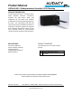
LCE20A-1000 – 20Amp Luminaire Controller 0-10V Dimming
ND xxxx-x 03/2017 Users Manual – LCE20A-1000 – 20Amp Luminaire Controller 0-10V Dimming
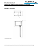
Connector Page 2
www.idealindustries.com
IDEAL Model LCE20A-1000 20Amp Luminaire Controller Installation
Instructions
WARNING: This is a current rated device. Use in applications involving
amperage beyond its rating can be dangerous and cause electrical fires.
Wiring must comply with all applicable electrical codes.
Turn off power before removing or installing connector.
TERMINOLOGY
LINE(Black): Smart Connector power feed to be connected to premise wiring
LOAD(Red): Power output from Smart Connector to ballast AC power input
Neutral(White): Incoming Neutral from premise wiring and outgoing ballast
neutral.
DIM (Purple/Grey): 0-10 VDC dimming control output from Smart Connector to
ballast dimming input
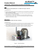
CONNECTING THE WIRES
Input Power
The smart connector LINE(Black) and NEUTRAL(White) wires are 18 AWG solid copper
conductors.
1. Strip wires to 1/2”.
2. Connect Smart Connector Line Input to premise line power feed with appropriate sized
wirenut or push-in connector.
3. Connect Smart Connector Neutral Input to premise neutral feed with appropriately sized
wirenut or push-in connector..
4. For feed-through (i.e., “daisy-chain”) installations, connect the LINE hot feed-through
conductor into the wirenut in step 2. Also, connect the NEUTRAL feet-through conductor
connected without re-installing the wires. into the wirenut in step 3.