
User's Manual

Product Manual
LCE20A-1000 – 20Amp Luminaire Controller 0-10V Dimming
ND xxxx-x 03/2017 Users Manual – LCE20A-1000 – 20Amp Luminaire Controller 0-10V Dimming
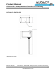
Connector Page 3
www.idealindustries.com
LOAD
The LOAD(red) and Neutral(White) wire are 18 AWG solid copper conductors.
1. Strip wires to 1/2”.
2. Connect Smart Connector LOAD wire to the ballast hot line with appropriate sized wirenut or
push-in connector if necessary.
3. Connect Smart Connector NEUTRAL Output to the ballast neutral with appropriately sized
wirenut or push-in connector if necessary.
4. For feed-through (i.e., “daisy-chain”) installations, connect the LOAD hot feed-through
conductor into the wirenut in step 2. Also, connect the NEUTRAL Output feed-through
conductor into the wirenut in step 3.
DIM Connector
The DIM wires are18 AWG solid copper conductors.
1. Strip wires to 1/2”.
2. Connect positive/(+)/purple DIM wire from Smart Connector to positive/(+)/purple wire from
dimming ballast with appropriate sized wirenut or push-in connector if necessary.
3. Connect negative/(-)/grey DIM wire from Smart Connector to negative/(-)/grey wire from
dimming ballast with appropriate sized wirenut or push-in connector if necessary.
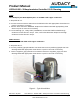
Figure 1 – Typical Installation