IDEAL INDUSTRIES, INC. TECHNICAL MANUAL MODEL: 61-340 MODEL: 61-342 Multimeter Service Information The Service Information provides the following information: • Precautions and safety information • Specifications • Basic maintenance (cleaning, replacing the battery and fuses) • Performance test procedures • Calibration and calibration adjustment procedures Form Number: TM61340-2 Revision: 2.
TABLE OF CONTENTS Page Introduction 1 Precautions and Safety Information 1 Symbols 1 Safety 2 Specifications 3 General Specifications 3 Measurement Characteristics 4 Voltage Specifications 4 Current Specifications 4/5 Resistance, Diode, Continuity, Capacitance Specifications 6 Frequency, Temperature Specifications 7 Auto Power Off, Data Hold/Backlight, SELECT, RANGE, REL, Hz/DUTY, MAX/MIN 7/8 Physical and Environment Characteristics 9 Certifications and Compliances 9 Required E
Page 1 Introduction Warning To avoid shock or injury, do not perform the verification tests or calibration procedures described in the manual unless you are qualified to do so. The information provided in this document is for the use of qualified personnel only. Caution The 61-340 serials contain parts that can be damaged by static discharge. Follow the standard practices for handling static sensitive devices. For additional information about IDEAL INDUSTRIES, INC.
Page 2 SAFETY Review the following safety precautions to avoid injury and prevent damage to this product or any products connected to it. To avoid potential hazards, use the product only as specified. For operating instructions, see the 61-340 / 61-342 Digital Multimeter Instruction Manual. CAUTION: These statements identify conditions or practices that could result in damage to the equipment or other property.
Page 3 SPECIFICATIONS All specifications are warranted unless noted typical and apply to the 61-340 & 61-342 Stated accuracies are at 23°C±5°C at less than 75% relative humidity and without the battery indicator displayed. General specifications Characteristics Description Display count 3 3/4 digit liquid crystal display, max count 4000 Numeric update rate 2.
Page 4 Measurement Characteristics Accuracy is ±(% reading + number of digits) at 23°C ± 5°C, less than 75% R.H. (1) DC Volts(for 61-340 / 61-342) Range Resolution Accuracy 400.0mV 0.1mV ±(0.8% reading + 3 digits) 4.000V 1mV 40.00V 10mV 400.0V 100mV 1000V 1V ±(1.0% reading + 3 digits) Range Resolution Accuracy 400.0mV 0.1mV ±(1.2%+8) 4.000V 1mV 40.00V 10mV 400.0V 100mV 750V 1V ±(0.
Page 5 (3b) DC Current (61-340 / 61-342) Range Resolution 4.000A 0.001A 10.00A* 0.01A Accuracy Input Protection ±(1.5% reading + 5 digits) 10A, 250V Fast Blow Fuse Overload Protection: A Input: 10A, 250V Fast Blow fuse. (61-340 / 61-342) *Caution: Do not make high current measurements on the 10A scale for longer that 15 seconds. This should be followed by a 15 minute cool down period. Exceeding 15 seconds may cause damage to the meter and/or the test leads.
Page 6 (5) Resistance (for 61-340 / 61-342) Over voltage protection Range Resolution Accuracy 400.0Ω *1 0.1Ω ±(1.2% reading + 5 digits) 4.000KΩ 1Ω 40.00KΩ 10Ω 400.0KΩ 100Ω 4.000MΩ 40.00MΩ * 2 ±(1.0% reading + 2 digits) 1KΩ ±(1.2% reading + 2 digits) 10KΩ ±(2.0% reading + 5 digits) 600Vrms Open circuit Voltage: 0.44V approx. *1 < 5 digit of reading rolling. *2 < 2% of reading rolling. (6) Diode Check and Continuity (for 61-340 / 61-342) Range Resolution Accuracy Max.
Page 7 (8) Frequency (for 61-340 / 61-342) Range Resolution 10.00Hz 0.01Hz 100.0Hz 0.1Hz 1.000KHz 1Hz 10.00KHz 10Hz 100.0KHz 100Hz 1.000MHz 10KHz 4.000MHz 10KHz Sensitivity Accuracy Overload protection 0.7V rms * Frequency: (± 0.1% + 3 digit) 600V rms 3.0V rms (9) Temperature: Type K thermocouple (for 61-340 / 61-342) Range Resolution Accuracy -50 to 750 ºC 1ºC ±3.0% ± 3 ºC -58 to1382 ºF 1ºF ±3.
Page 8 (14) REL Press this button the meter enter relative measuring state and “Δ” symbol appear on LCD. The result of the relative measurement is the difference between measuring value and reference value. The reference value is produced same as momentary reading value when pressing this button, press it again to exit this state and “Δ” symbol disappear on display, and this button do not effect on frequency, diode and continuity test function.
Page 9 Physical and Environmental Characteristics Characteristics Description Dimensions (H×W×D) 180mm(H) ×91mm (W) ×43mm(D) (with holster) 7.1” (H) x 3.6”(W) x1.7”(D) Weight (with battery& holster) 0.379Kg (13.4 oz.) Environmental characteristics Description Temperature operating 0 to +40°C Non-Operating -20 to +60°C <75% R.H. Humidity (operating) <70% R.H. Altitude 6561.7 Ft.
Page 10 Required Equipment Required equipment is listed in Table B. If the recommended models are not available, equipment with equivalent specifications may be used. Repairs or servicing should be performed only by qualified personnel. Table B. Required Equipment Equipment Calibrator Required Characteristics AC Voltage Range: 0 ~ 750V AC Accuracy: ±0.07% (Basic) Frequency Range: 40 ~ 1KHz Accuracy: ±2% DC Voltage Range: 0 ~ 1000V DC Accuracy: ±0.
Page 11 Basic Maintenance Warning To avoid shock, remove the test leads and any input signals before opening the case or replacing the battery or fuses. Opening the Meter Case Caution To avoid unintentional shock circuit, always place the uncovered meter assembly on a protective surface. When the case of the meter is open, circuit connections are exposed. 1. Disconnect test leads from any live source, turn the rotary switch to OFF, and remove the test leads from front terminals. 2.
Page 12 Replacing Fuses Warning To avoid electrical shock, remove the test leads and any input signals before replacing the battery or fuses. To prevent damage or injury, INSTALL ONLY quick acting fuses with the following Volt/Amp current interrupt rating: F340: 500mA, 250V Fast Blow Fuse F342: 10A, 250V Fast Blow Fuse Fuse Replacement The 61-340 and 61-342 are fused in both the μA /mA input and 10 amperes input ports.
Page 13 Performance Tests The following performance tests verify the complete operability of the meter and check the accuracy of each meter function against the meter’s specifications. For operating instructions, see the 61-340 / 61-342 Digital Multimeter Instruction Manual. Accuracy specifications are valid for a period of one year after calibration, when measured at an operating temperature of 18°C to 28°C and a maximum of 75% relative humidity.
Page 14 Testing the Voltage Function (for 61-340 / 61-342) To verify accuracy in the AC and DC voltage ranges, do the following: 1. Turn the rotary switch to “ ” position. 2. Connect the calibrator to the and COM inputs on the meter. 3. Set the calibrator for the voltage from step 1 to 7 in Table 1. 4. Compare the reading on the meter display with the display reading shown in Table 1. 5. If the display reading falls outside of the range shown in Table 1, the meter does not meet specification.
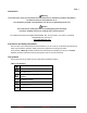
Page 15 Table 2 AC Voltage Test: Step Range Input Frequency Reading 61-340 Reading 61-342 1 400mV 300mV 60 295.6 to304.4 295.6 to304.4 2 400mV 300mV 400 295.6 to304.4 295.6 to304.4 3 4V 3.000V 60Hz 2.965 to 3.035 2.965 to 3.035 4 4V 3.000V 400Hz 2.965 to 3.035 2.965 to 3.035 5 40V 30.00V 60Hz 29.65 to 30.35 29.65 to 30.35 6 40V 30.00V 400Hz 29.65 to 30.35 29.65 to 30.35 7 400V 300.0V 60Hz 296.5 to 303.5 296.5 to 303.5 8 400V 300.0V 400Hz 296.5 to 303.
Page 16 Table 3b DC mA Test: Step Range Source Reading 1 40mA 30.00mA 29.73 to 30.27 2 400mA 300.0mA 297.3 to 302.7 Testing the DC ampere Function (for 61-340 and 61-342) 1. Connect the calibrator to the 10A and COM inputs on the meter. 2. Turn the rotary switch to . a. Press the SELECT button to select the DC function 3. Apply the inputs for steps 1-2 in Table 3c. 4. For each input, compare the reading on the meter display to the reading for your meter in Table 3c 5.
Page 17 Testing the AC milliampere function: (for 61-340and 61-342) 1. Connect the calibrator to the and COM inputs on the meter. 2. Turn the rotary switch to . a. Press the SELECT button to select the AC function b. Press the REL button to make the display is zero 3. Apply the inputs for steps 1-4 in Table 4b. 4. For each input, compare the reading on the meter display to the reading for your meter in Table 4b 5.
Page 18 Testing the Resistance Function (for 61-340 / 61-342) To verify the accuracy of the resistance function, do the following: and COM on the meter. 1. Connect the calibrator to 2. Turn the rotary switch to . a. Press the SELECT button to select the Ω function 3. Apply the inputs for step 1-7 in Table 5. 4. Compare the meter display readings to the display readings in Table 5. 5. If the display reading falls outside of the range shown in Table 5, the meter does not meet specification.
Page 19 Table 6 Capacitance Test: Step Range Source Reading 1 40nF 10.000nF 9.60 to 10.40 2 40nF 30.00nF 29.00 to 31.00 3 400nF 300.0nF 290.5 to 309.5 4 4µF 3.000µF 2.905 to 3.095 5 40.00µF 30.00µF 29.05 to 30.95 6 100.0µF 100.0µF 79.5 to 120.5 7 1000µF 1000µF 795 to 1205 Checking the Diode Test Function (for 61-340 / 61-342) To check the diode test function, do the following: 1. Connect the DVM (Digital Voltage Meter) to the 2.
Page 20 Testing the Frequency Function (for 61-340 / 61-342) To verify the accuracy of the meter’s frequency function, do the following: 1. Connect the calibrator to the and COM inputs on the meter. 2. Note: The accuracy of the calibrator’s frequency function must be appropriate for the specified accuracy of the meter. 3. Set the rotary switch to . 4. Set the calibrator or function generator for the square wave voltage and frequency for steps 1-6 of Table 7a. 5.
Page 21 Testing the Temperature Function (for 61-340 / 61-342) To verify the accuracy of the meter’s temperature function, do the following: 1. Connect the calibrator to the 2. 3. 4. 5. and COM inputs on the meter. Set the rotary switch to the ºF / ºC as instructed in Table 8. Set the calibrators temperature output to the source values in Table 8, for steps 1-7. Compare the reading on the meter display with the display reading shown in Table 8.
Page 22 Calibration Procedure Recalibrate your meter: It is recommended that the multimeter be calibrated once each year. 1. Perform calibration at an ambient temperature of 23°C±2°C and a relative humidity of <70% Disconnect the test leads and turn the meter off. Remove the test leads from the front terminals. 2. Position the meter face down. Remove the battery cover screw and the 2 bottom case cover screws. 3.
Page 23 6. Using a small flat-tipped screwdriver, adjust VRtr until the display reads 2.995 to 3.005Volts 7. Disconnect the AC calibrator from the meter. (C) TEMP Calibration (Adjust VR3) 1. Set the rotary switch to the " ºF/ ºC " position. 2. Set the output of the calibrator to 300 ºC 3. Connect the calibrator temperature output to the and COM input terminals 4.