
Instructions / Assembly

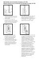


2. Place circuit breaker in the OFF
position. Ensure locking cleat
inserts into the recessed area of
the circuit breaker.
2. Coloque el cortacircuitos en la
posición OFF (apagada).
Asegúrese de que el
estabilizador se inserte en el
área rebajada del cortacircuitos.
3. Electrically verify associated
circuitry is de-energized. Rotate
thumb wheel clockwise to
secure lock-out device to the
circuit breaker switch tongue.
Verify that the circuit breaker
switch tongue CANNOT be
rotated to ON.
3. Verifique eléctricamente que los
circuitos asociados estén de-
senergizados. Gire la ruedecilla
hacia la derecha para asegurar
el dispositivo de bloqueo a la
lengüeta del cortacircuitos.
Verifique que la lengüeta de
interruptor del cortacircuitos NO
PUEDA ser girada a la posición.
Warranty limited solely to repair or replacement; no warranty of merchantability, fitness for a particular purpose or consequential
damages.
IDEAL INDUSTRIES, INC.
Sycamore, IL 60178, U.S.A.
800-435-0705 Customer Assistance / Asistencia al cliente
www.idealindustries.com
IA 3132-2 Assembled In U.S.A. Of U.S. And Global Components
4. Attach pad lock as required.
Hang workmans protective tag
as required.
4. Coloque un candado segün sea
requerido. Cuelgue un rótulo
protector de identificación
del trabajador segün sea
requerido.
277 Volt - 480/600 Volt Locking Cleat Installation Procedure (44-1807 and 44-1809)
1. Snap the Locking Cleat to the
base of the Lock-Out device
as shown.
1. Enganche el estabilizador
a la base del dispositivo de
bloqueo tal como muestra.