
Installation Guide
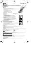

Vol-Con
®
Elite Voltage / Continuity Tester with Audible and
Visual Indicators
WARNING
Safety Information:
• Before each use perform a continuity test by touching the probe tips together, an audible sound should be heard and the continuity
LED should light. This test verifies the functionality of the battery and test leads.
• Verify tester operation before each use by measuring a known voltage.
• Visually inspect the meter and leads for damage before each use. Replace leads if insulation is damaged or leads appear suspect.
• Voltage is not to exceed 1000V.
• To avoid electrical shock hazards and/or damage to the meter:
- Never ground yourself when taking electrical measurements.
- Use caution when measuring voltage.
- Do not use during electrical storms.
- Turn off power to the circuit or device before testing for continuity.
- Do not use in wet weather.
• Test Non-Contact Voltage function on known live voltage before using.
Features:
• Noncontact Voltage Sensor • Auto-Switching Voltage/Continuity Technology
• Vibration Mode (61-092) • Low Impedance Measuring Device
• Audible and LED Indication of Voltage Levels • Replaceable Silicone Test Leads
To Measure AC Voltage:
• Place the black test lead into the "COM" input and the red test lead into the "v+" input on the tester.
• Connect the tester in parallel with the load or circuit.
• The tester will automatically turn on, indicating both the voltage type and the voltage level.
To Measure DC Voltage:
• Place the black test lead into the "COM" input and the red test lead into the "v+" input on the tester.
• Connect the tester in parallel with the load or circuit.
• The tester will automatically turn on, indicating the voltage type, polarity, and the voltage level.
To Test for Continuity:
• Place the black test lead into the "COM" input and the red test lead into the "v+" input on the tester.
• De-Energize circuit before performing continuity test. Note, if voltage is present in the circuit, the tester
will automatically switch to voltage indication mode.
• Test for continuity by connecting the meter to the circuit.
• If circuit is complete, an audible indication will be heard and the Continuity LED will light.
• Continuity is indicated at less than 20kΩ.
To Use The Non-Contact Voltage Sensor:
• The non-contact voltage sensor indicates AC Voltage from 24 to 600 VAC.
• The non-contact voltage sensor protrudes from the top of the tester.
• While placing the sensor near the circuit to be tested, press the button labeled "NCV".
• If 24 to 600 VAC is present, an audible indication will be heard and the "NCV" LED will light.
• The closer the NCV sensor is to the AC voltage, the louder the beep.
• To differentiate between the hot and neutral in an outlet, insert the tab into each slot of the outlet. The beeper will be louder on
the hot side of the outlet rather than the neutral.
• The red test lead can also be used to further differentiate between the hot and neutral. Insert the red test lead into the "v+"
input of the tester, slide the red probe into test probe holder. While pressing the "NCV" button, insert the red probe into the
outlet. The beeper will sound and the "NCV" LED will light on the hot side of the outlet.
Shaker Function:
61-092 Only
• Tester vibrates on AC Volts.
• Tester starts shaking at 30VAC.
• The tester shakes at an increasingly variable level that allows the user to feel the difference between 60V, 120V, 240V, and 480 VAC.
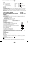
V+ Input Terminal
This is the positive input terminal. Connection is made to it using the red test lead.
COM Input Terminal
This is the negative (ground) input terminal. Connection is made to it using the black test lead.
Safety Information
The instrument complies with class II, overvoltage CAT III, 1000V of the IEC 1010-1 (EN61010-1); UL3111-1 and CAN/CSA C22.2 #1010.1-92 standards. Pollution degree 2 in accordance with
IEC-664 indoor use. If the equipment is used in a manner not specified, the protection provided by the equipment may be impaired.
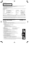
The symbols used on this instrument are:
Caution, refer to accompanying documents Direct current
Equipment protected throughout by Double insulation (Class II) Ground
Alternating current
Maintenance
Maintenance consists of periodic cleaning and battery replacement. The exterior of the instrument can be cleaned with a dry clean cloth to remove any oil, grease or grime. never use liquid
solvents or detergents. Repairs or servicing not covered in this manual should only be performed by qualified personnel.
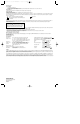
Replacing the Battery
This meter is powered by four 1.5 volt (AAA size) batteries. (Total Voltage: 6Vdc, Total Current: 120mA) When the meter is not able to perform the continuity test, the battery must be
replaced to maintain proper operation. Use the following procedure to replace the battery:
1. Disconnect test leads from any live source and remove the test leads from the input terminals.
2. The battery cover is secured to the bottom case by two screws. Using a Phillips-head screwdriver, remove the screws from the battery cover and remove the battery cover.
3. Remove battery and replace with four new 1.5 volt (AAA size) batteries.
4. Replace the battery cover and reinstall the screws.
Service, and Replacement Parts:
For replacement parts or to inquire about service information contact IDEAL INDUSTRIES, INC. at 1-800-304-3578 or visit our website www.testersandmeters.com.
Test Leads - TL-102
Soft sided carrying case - C-90
#61-090 NCV
#61-092 NCV, Shaker
~
Warning
To avoid electrical shock, disconnect the test leads and any input
signals before replacing the battery. Replace only the same type of
battery.
ND 3039-3 61-090/092 Instructio 7/1/04 10:48 AM Page 1