
Instructions / Assembly


61-534
Automatic Circuit Identifier
With Digital Receiver and
120V GFCI Receptacle Tester
The task of locating AC circuits is now made quick and easy. No more guessing
or trial and error when it comes to locating the correct circuit breaker supplying
power to an AC outlet or lighting fixture.
WARNING: Read and understand operating instructions before using product.
WARNING: Use extreme care when working around AC circuits, severe shock
hazards exist. If used on a circuit controlled by a dimmer, turn the dimmer to the
highest on position. Do not use in cardiac care areas.
Features:
• Automatically and quickly finds correct breaker
• Non-contact voltage sensor from 80-300VAC
• Transmitter works on 120VAC circuits
• Tests GFCIs
• Verifies wiring configuration
• Low battery indicator
OPERATION:
Self-Test
Depress the receiver’s power switch forward to the ON position. The unit will perform a self-test to
ensure proper operation.
Low Battery Detection
After performing the self-test, the receiver will verify the voltage of the 9Vdc battery. If the battery voltage is below 7.3 volts, the
receiver will beep three times and turn itself off. Remove the old battery, and replace it with a standard 9Vdc battery.
Idle Mode
Provided the battery is good, the receiver will enter the idle mode. Both the receiver’s LEDs will remain on and the receiver will
continually check for any active signals.
Non-Contact Voltage Test
Point the receiver’s nose towards a live AC receptacle or power cord. Once an AC Voltage field of > 80V is sensed, the receiver will
switch to Voltage Sensor mode. The red LED remains lit and the receiver will beep. The beeping speed increases when the receiver
is moved closer to the AC power source, and slows when the receiver is moved further away. Once the receiver senses a signal
from the transmitter, it will switch to the circuit identifier mode. The circuit identifier mode is indicated by a steady green LED.
Locating A Circuit Breaker or Fuse:
1. Plug the transmitter into the receptacle.
2. Go to the circuit breaker panel box.
3. Turn the receiver on and allow it to complete its self-test away from power.
4. Place the flat surface of the tapered end of the receiver directly onto the circuit
breaker or fuse as shown. If the receiver is held at any other angle, inaccurate
readings may occur.
5. Slide the nose of the receiver down each breaker along both sides of the panel. Note
that the receiver will beep frequently as it measures the relative signal strength.
6. Move the receiver down each breaker once more. On the second pass, the receiver
will beep and the green LED will flash only at the circuit breaker powering
the transmitter.
7. Trip the breaker off and check that the LED’s of the transmitter in the outlet are off to confirm you have selected the correct
breaker or fuse.
Locating a Circuit Breaker or Fuse Controlling an Incandescent Light Fixture
1. If the incandescent light fixture is controlled by a wall switch, make sure the wall switch is OFF.
2. Remove light bulb.
3. Install a Screw-in socket adapter (not included).
4. Plug the transmitter into the adapter.
5. Turn on the wall switch and follow the procedure described in Locating a Circuit Breaker or Fuse, steps 3 through 7.
Receiver Auto Power Off:
If the receiver is left on and not utilized for 10 minutes (no energized AC circuit or transmitter signals are detected), it will
automatically shut down to conserve its battery life.
Battery Replacement:
Unscrew and remove battery cover. Insert new 9V battery into battery compartment and re-install battery cover.
Verifying Receptacles for Correct Wiring:
Plug the transmitter into a standard 120 VAC receptacle. The three LEDs on the transmitter will indicate the wiring configuration
while the label on the transmitter interprets the LED lighting combinations.
Caution: The tester is for indication purposes only and a correct indication does not guarantee the integrity of the wiring. Any
incorrect or unclear indications should be referred to a licensed electrician for investigation and correction.
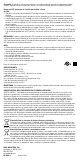
Power Switch
Battery Compartment
Red LED
Green LED
LEDs