SURETRACE ™ CIRCUIT TRACER Your IDEAL troubleshooting solution. Designed to find everything, while saving you time and money.
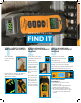
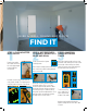
FINDING ENERGIZED BREAKERS AND FUSES BREAKER OR FUSE FIND IT STEP 1: VERIFY POWER AND SIGNAL ON CIRCUIT STEP 2: SCAN EACH STEP 3: SCAN EACH PANEL FOR THE HIGHEST BREAKER FOR HIGHEST READING READING Plug Transmitter into an outlet and power on. Set Receiver to the highest sensitivity mode (Receiver defaults to this). Set Receiver to the lowest sensitivity mode (also known as Breaker mode). Place Receiver flat on the front near the top of each panel until the highest reading is reached.
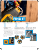
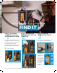
COMMON SPLICE ERROR FIND IT STEP 1: ATTACH CLIPS STEP 2: SCAN STEP 3: SEPARATE NEUTRALS 1. Confirm branch circuits are de-energized 2. Use a continuity check to determine which conductors are affected 3. Attach Transmitter alligator clips to the affected breaker neutrals.(The two neutrals of the AFCI/GFCI/Combo Breakers that are nuisance tripping) Scan each electrical location (switch, outlet, light fixture, etc.
DEAD SHORT FIND IT STEP 1: DETERMINE THE SHORTED CONDITION STEP 2: ATTACH CLIPS AND SET RECEIVER’S SENSITIVITY STEP 3: SCAN 1. Confirm branch circuit is de-energized. 2. Unplug all items connected to the affected branch circuit. 3. Verify the fault is in the affected branch circuit. 4. Use a continuity check to determine which conductors are affected. Set Receiver to the first, or highest, sensitivity mode.
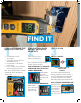
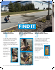
WIRE IN WALL, CEILING AND FLOOR FIND IT STEP 1: PLUG ADAPTER INTO CIRCUIT STEP 2: SET RECEIVER TO HIGHEST SENSITIVITY MODE AND SCAN Plug the transmitter into a wall outlet using the outlet plug adapter provided with the circuit tracer. Set the receiver to the highest sensitivity mode. Hold the receiver near the transmitter to verify signal strength. The lightning bolt indicates power is present on the circuit.
BURIED CONDUCTOR FIND IT STEP 1: ATTACH ALLIGATOR CLIPS STEP 2: PLUG LEADS INTO TRANSMITTER AND TURN IT ON Use appropriate methods and LO/TO to ensure the conductors are de-energized and locked out before proceeding. Verify that you de-energized the correct conductors before proceeding when possible. Re-energize after the transmitter is attached. Using appropriate safety methods, attach the alligator clips with 3 ft. leads to the Hot and Neutral conductors on the supply side of the branch circuit.
3-PHASE BREAKER, FUSE, CONDUCTOR FIND IT STEP 1: ATTACHING ALLIGATOR CLIPS TO LIVE 3-PHASE SYSTEMS STEP 2: PLUG LEADS INTO TRANSMITTER AND TURN IT ON Using appropriate safety methods, attach the alligator clips with 3 ft. leads to any two of the three phases. (ensure leads are not plugged into the transmitter) Next, plug opposite ends of leads into the transmitter starting with the black lead first.
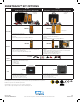
SURETRACE™ KIT OPTIONS 61-946 SureTrace™ Circuit Tracer 0-480V AC/DC 61-948 SureTrace™ Plus Circuit Tracer 0-600V AC/DC Residential Commercial Commercial Industrial Voltage Level Indicator TR-946 TR-948 Continuity Test Transmitter* • • • • CAT III 480V, Range 0-480V AC/DC Indicators: Power, Energized Circuit, CertainCircuit™, Battery Level Kickstand Magnetic Hanging Strap Clip (sold separately, UMHS-757) • • • • • CAT III 600V, Range 0-600V AC/DC Indicators: AC/DC Voltage and DC Polarity, Power, E