#61-955 #61-957 #61-959 SureTrace™ Circuit Tracers Instruction Manual Register your product and access more information at www.idealindustries.
Table of Contents • Safety Information................................................................................... 3 • Introduction............................................................................................. 4 • Callouts of Features • • • • Transmitter.............................................................................................................5 Receiver.................................................................................................................
Read first: Safety Information Understand and follow operating instructions carefully. Use the tracer only as specified in this manual; otherwise, the protection provided by the tracer maybe impaired. WARNING To avoid electric shock, personal injury, or death, follow these instructions: • Before using or connecting the tracer, visually inspect to ensure the cases are not cracked and back case is securely in place. Do not use if tracer appears damaged.
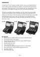
Introduction The SureTrace™ Circuit Tracers are powerful, versatile, easy-to-use troubleshooting test tools for finding breakers and hidden wire problems in residential/commercial/industrial environments. These tracers work on closed (energized) and open (de-energized) circuits. They identify circuit breakers, find opens and shorts, and trace wires behind walls. The tracers are available in three configurations. Each kit contains the same transmitter (TR-955) and test lead kit (TL-956).
Transmitter Callout Features 1 1. Output Jacks Non-polarized, standard banana plug type. 2. Power Indicator When the transmitter is On, the LED illuminates indicating that a signal is being produced. 3. Line Energized Indicator The transmitter continuously monitors the voltage across its output terminals. If greater than 30 volts AC or 40 volts DC is present, the LED indicator illuminates. The transmitter also communicates the line voltage state to the receiver. 4.
Receiver Callout Features 1. Super Bright Display See next page for features. 2. Sensitivity Mode: Depress this button to select the mode of sensitivity*: Mode RC-955 RC-959 Antenna Strength 4 highest sensitivity (default mode) 1 3 high-medium sensitivity 2 medium-low sensitivity lowest sensitivity for breakers 1 * See Additional Notes on next page for guidelines on mode selection. 2 3 4 5 3. Audible Indication RC-955 6 Depress this button to turn the sound On/Off.
RC-955 Display 1. Bright, 2-digit LED display. (180° Rotating) 2. Displays the powered line status received from the transmitter. 3. “0-99” numeric indication of signal strength. 4. Indicator lights when audible tone 3 is disabled. 5. Peak detector shows instantaneous changes in signal strength. 2 1 4 RC-959 Display 4 1. Super-bright OLED display (90° rotating). 2. Displays the powered line status received from the transmitter. 2 3. Indicates On/Off status of the audible tone. 4. Low Battery Indicator.
• Receiver Orientation • The indication of received signal intensity depends on how the receiver is pointed in relation to the source of the signal. If the receiver is pointed away from the signal source then there will be a low value indicated on the receiver. If the receiver is rotated about the axis of main antenna sensitivity, the signal varies in strength as the antenna is pointed at and then away from the circuit being traced.
Inductive Clamp (IC-958) with Battery Pack (BP-958) Callout Features 1. 2. 3. 4. 5. 6. 7. 1” (25mm) Jaw Opening. Powerful coil induces a low voltage signal onto a closed circuit. 6’ cord attaches to the battery pack for power. Protective case. (8) C-cell batteries. Input jack for clamp cord. Hang mount for magnetic strap. Magnetic Strap (not shown) • Hooks onto the battery pack. • Magnet attaches to metal cabinets, panels, electrical boxes, etc.
Here are some examples of Open/Closed Circuits: Closed Loop Closed Loop Stronger Stronger Open Loop Weaker Breaker Energized Breaker Energized Closed Loop Stronger Closed Loop Open Loop Stronger Weaker Open Loop Weaker Breaker De-Energized Breaker Energized Light On (Load) Remote Return Path Electromagnetic fields radiate counter-clockwise in relation to the current flow. For example, current flows out on a hot conductor and returns on the neutral.
To avoid the canceling effect of the opposing magnetic fields and optimize the transmitted signal, the conductor to be traced should be separated from the return conductor by utilizing a remote return path. The simplest method is to use the 25’ test lead to connect to a remote return path, such as a neutral or ground from another circuit or a water pipe. When identifying breakers, the hot and neutral are already separated at the electrical panel so the use of the AC outlet adapter is sufficient.
Locating Circuit Breakers and Fuses Applications include identifying the breaker that protects the circuit under test, finding the correct breaker to de-energize the circuit, and labeling a breaker panel. 1) 2) 3) 4) 5) Connect the transmitter to the circuit that needs to be identified and power it on. The procedure is the same whether the circuit is energized or de-energized. But, a much stronger signal is produced using an energized (closed) circuit. Turn on the receiver and go to the panel.
Tracing Wires Applications include finding the locations of cable runs and identifying other devices and loads on the circuit. 1) 2) 3) 4) Connect the transmitter to the circuit to be traced and power it on. a) For optimal tracing, leave the circuit energized to create a closed loop. b) If the circuit is de-energized, then connect transmitter to the neutral and ground conductors to create a closed loop. Turn on the receiver and use the default maximum sensitivity ( ).
Finding Opens Applications include locating dead circuits, finding the source of an open (broken point) in a hot/neutral/ground conductor, and determining the end of a circuit run. 1) 2) 3) 4) Connect the transmitter to the open circuit and power it on. Turn on the receiver and use the default maximum sensitivity. Starting several feet from the transmitter, use a sweeping motion and the back of the receiver to find the strongest signal location behind the wall, above the ceiling or under the floor.
Finding Shorts Applications include determining causes of breakers tripping, fuses blowing, and current leaking on the ground conductor. The tracer locates the origin of the ground fault or deadshort in these circuits. 1) 2) 3) 4) Connect the transmitter to the shorted circuit and power it on. a) One lead should be connected to the faulted conductor and the other lead to ground. b) If the ground fault is in metallic conduit, then the conduit is the ground. c) If possible, ground the adjacent conductors.
Sorting Bundled Wires Applications include identifying a specific circuit amongst several circuits in a filled conduit, sorting wires in a wire harness, identifying coax cable and twisted pair cable in a termination box. 1) 2) 3) 4) Connect the transmitter to the circuit to be traced and power it on. a) Clip one test lead to the known end of the wire to be traced or identified. b) Clip the other test lead to a remote return path. Turn on the receiver and set it to the least sensitivity ( ).
Tracing Underground These circuit tracers are not underground cable locators. But, in some environments they can be used to trace buried cables, conduit, or metal pipe. 1) Connect the transmitter to the circuit to be traced and power it on. a) If possible, create a closed circuit by grounding the other end. b) If possible, ground the adjacent conductors to eliminate capacitive-coupling effects that can cause signal bleed-over. c) Utilize a remote return path to maximize the signal produced.
Inductive Clamp Applications WARNING: The clamp does not have any indicators to sense if a circuit is energized. The line energized feature ( ) on the receiver only works with the transmitter (TR-955). The inductive clamp is powered solely by the battery pack. It generates its own specific, time modulated signal, and by transformer action, couples that signal onto the energized or de-energized circuit to be traced. Always disconnect the battery pack from the clamp when not in use to conserve battery power.
Identifying downstream loads from a breaker. 1) Remove the panel cover and clamp around the hot wire of the energized (closed) circuit. • To maximize the signal, close the far end of the circuit by plugging in and turning on a work light or other load into the furthest outlet; hence, making a complete loop. 2) Hang the battery pack onto the panel with the magnetic strap. 3) Plug the clamp into the battery pack.
3) 4) Plug the clamp into the battery pack. Set the receiver to the highest sensitivity ( ) mode and trace the conduit. If the Receiver is saturated, reduce the sensitivity range. Tracing industrial control circuits. 1) Ensure that the circuit is energized (closed at the panel) at a minimum. To maximize the signal, close the other end of the circuit by turning on a load, such as a motor or pump. 2) Clamp around the hot wire of this energized (closed) circuit.
Receiver: 1) Remove the battery cap by loosening the screw. 2) Replace batteries with (3) new AA batteries. 3) Re-fit cap and re-tighten the screw. Battery Pack for Inductive Clamp: Ensure the clamp is unplugged from the battery pack. 1) Remove cap by squeezing the ribbed tabs on either side of the cap. 2) Remove the battery holder noting the orientation to the strap mount on the case. 3) Replace batteries with (8) new C-cell batteries.
Maintenance Clean the case with a damp cloth and mild detergent. Do not use abrasives or solvents. Keep away from liquids and ensure the tracer is completely dry before use. Service and Replacement Parts This unit has no user-serviceable parts except for the fuse in the transmitter. For replacement parts or to inquire about service, contact IDEAL Technical Support at 877-201-9005 or visit our website, www.idealindustries.com.
Specifications (continued): Circuit Tracer Kits Operating Temperature: Storage Temperature: Humidity (Operating): Dimensions (W x H x D) Weight: Accessories Included: Safety: 32°F (0°C) to 122°F (50°C) -4°F (-20°C) to 140°F (60°C) (without batteries installed). 95% R.H. max 61-955/957: 14.0 x 11.3 x 3.3 in. (355 x 285 x 83 mm) 61-959: 18.5 x 14.6 x 3.5 in. (470 x 371 x 89 mm) 61-955/957: 4.5 lbs. (2.1 kg) 61-959: 7.9 lbs. (3.
Warranty Statement: This tester is warranted to the original purchaser against defects in material and workmanship for two years. During this warranty period, IDEAL INDUSTRIES, INC. will, at its option, replace or repair the defective unit, subject to verification of the defect or malfunction. This warranty does not apply to defects resulting from abuse, neglect, accident, unauthorized repair, alteration, or unreasonable use of the instrument.
#61-955 #61-957 #61-959 Rastreadores de circuitos SureTest® Manual de Instrucciones Registre su producto y acceda a más información en www.idealindustries.
Índice • Información relacionada con la seguridad ............................................. 3 • Introducción ........................................................................................... 4 • Características • • • • Transmisor ...........................................................................................................5 Receptor ...............................................................................................................6 Juego de cables de prueba .........
Lea primero: Información relacionada con la seguridad Asegúrese de entender y seguir cuidadosamente las instrucciones de operación. Use el rastreador sólo como se especifica en este manual. De lo contrario, la protección que proporciona el mismo puede resultar perjudicada.
Introducción Los rastreadores de circuitos SureTest® son herramientas de prueba y resolución de problemas potentes, versátiles y fáciles de usar para la localización de disyuntores y de problemas de conductores ocultos en ambientes residenciales, comerciales e industriales. Estos rastreadores funcionan en circuitos cerrados (energizados) y abiertos (desenergizados). Identifican disyuntores, localizan circuitos abiertos y cortocircuitos, y rastrean conductores detrás de las paredes.
Características del transmisor 1 1. Jacks de entrada Enchufes tipo banana estándar no polarizado. 4 2. Indicador de encendido Cuando el transmisor está encendido, el LED se 2 ilumina para indicar que se está produciendo una señal. 3 3. Indicador de línea energizada El transmisor monitorea los voltajes en sus terminales de entrada continuamente. Si hay voltajes mayores a 5 30 voltios CA o 40 voltios CD, el indicador LED se enciende.
Características del receptor 1. Pantalla súper brillante Vea las características en la página siguiente. 2. Modo de sensibilidad: Pulse este botón para seleccionar el modo de sensibilidad*: Modo RC-955 RC-959 Intesidad en antea 4 máxima sensibilidad (modo por defecto) 1 3 ala-mediana sensibilidad 2 mediana-baja sensibilidad 2 3 1 mínima sensibilidad para disyuntores * Vea las pautas de selección del modo en Notas adicionales de la página siguiente. 3.
Pantalla RC-959 1 4 1. Pantalla súper brillante de LED que hace girar el valor numérico. 2. Recibe del transmisor el estado de la línea alimentada. 2 3. Indica el estado de activación/desactivación de la función audible. 4. El indicador de baterías con poca carga está 3 encendido y destella cuando queda un 10% de vida útil remanente. 5 6 7 5. Indicación numérica “0-99” de la intensidad de señal. 6. Muestra el modo de sensibilidad. 7.
Juego de cables de prueba (TL-956) Se provee un juego completo de cables de prueba para usar con el transmisor. 1 2 3 1. Adaptador TLOP-956 enchufable en tomacorrientes estándar de 120 VCA. 2. (2) terminales TLBP-956 para insertar en un tomacorriente separado con un conductor neutro remoto como trayecto de retorno. 3. Terminal de tierra TLGP-956 para insertar en un tomacorriente separado con conductor de tierra remoto como trayecto de retorno. 5 6 4 4.
Características de la pinza inductiva (IC-958) with conjunto de baterías (BP-958) 1. 2. 3. 4. 5. 6. 7. 1 Abertura de mandíbula de 25 mm (1 pulg.). El poderoso electroimán induce una señal de baja tensión en un circuito cerrado. El cordón de 1,80 m (6 pies) se conecta al conjunto de baterías para alimentación. Carcasa protectora. (8) baterías de celda C. Jack de entrada para el cordón de la pinza Montaje colgante para tira magnética. Tira magnética (no se muestra) • Se engancha al conjunto de baterías.
He aquí algunos ejemplos de circuitos abiertos y cerrados: Lazo cerrado Lazo abierto Más intensa Más débi Lazo cerrado Más intensa Disyuntor energizado Disyuntor energizado Lazo cerrado Lazo cerrado Más intensa Más intensa Lazo abierto Más débi Lazo abierto Más débi Disyuntor is-energizado Disyuntor energizado Luz encendida (carga) Trayecto de retorno remoto Los campos electromagnéticos se irradian en sentido antihorario en relación al flujo de corriente.
Para evitar el efecto de cancelación de los campos magnéticos opuestos y optimizar la señal transmitida, el conductor a rastrear debe separarse del de retorno utilizando un trayecto de retorno remoto. El método más sencillo consiste en utilizar el cable de prueba de 7,5 m (25 pies) y conectarlo a un trayecto de retorno remoto, tal como el neutro o la tierra de otro circuito o una tubería de agua.
Localización de disyuntores y fusibles Las aplicaciones incluyen la identificación del disyuntor que protege al circuito en prueba, la localización del disyuntor correcto que desenergiza el circuito y la rotulación de un tablero de disyuntores. 1) 2) 3) 4) 5) Conecte el transmisor al circuito que se debe identificar y enciéndalo. El procedimiento es el mismo ya sea que el circuito esté energizado o desenergizado.
Rastreo de conductores detrás de las paredes Las aplicaciones incluyen la localización de las ubicaciones de tramos de cables y la identificación de otros dispositivos y cargas presentes en el circuito. 1) 2) 3) 4) Conecte el transmisor al circuito que se debe rastrear y enciéndalo. a) Para un rastreo óptimo, deje el circuito energizado para crear un lazo cerrado. b) Si el circuito está desenergizado, conecte el transmisor a los conductores neutro y de tierra, para crear un lazo cerrado.
Localización de circuitos abiertos Las aplicaciones incluyen la localización de circuitos sin alimentación, la búsqueda del origen de un circuito abierto (punto de interrupción) en un conductor vivo/neutro/tierra y la determinación del extremo de un tramo de circuito. 1) 2) 3) 4) Conecte el transmisor al circuito abierto y enciéndalo. Encienda el receptor y use la sensibilidad máxima por defecto ( ).
Localización de cortocircuitos Las aplicaciones incluyen la determinación de las causas de disparo de disyuntores, fusión de fusibles y fugas de corriente por el conductor de tierra. El rastreador localiza el origen de la falla de tierra o el cortocircuito con resistencia cero en estos circuitos. 1) 2) 4) Conecte el transmisor al circuito en corto y enciéndalo. a) Un cable se debe conectar al conductor con falla y el otro a tierra.
Clasificación de manojos de conductores Las aplicaciones incluyen la identificación de un circuito específico entre varios circuitos alojados en un conducto lleno, la clasificación de cables en un arnés y la identificación de cables coaxiles y de par retorcido en una caja de terminación. 1) 2) 3) 4) Conecte el transmisor al circuito que se debe rastrear y enciéndalo. a) Enganche la pinza de un cable de prueba al extremo conocido del conductor a rastrear o identificar.
Rastreo subterráneo Estos rastreadores de circuitos no están previstos para localizar cables subterráneos. No obstante, en algunos entornos se pueden usar para rastrear cables, conductos o tubos metálicos enterrados. 1) 2) 3) 4) Conecte el transmisor al circuito que se debe rastrear y enciéndalo. a) Si es posible, cree un circuito cerrado poniendo a tierra el otro extremo.
Aplicaciones de la pinza inductiva ADVERTENCIA: La pinza no tiene indicadores para detectar si un circuito está energizado. Así que, la característica de energizado ( ) en el receptor solo funciona con el transmisor (TR-955). La pinza inductiva se alimenta solamente con el conjunto de baterías. Genera su propia señal específica, modulada en el tiempo, que, por acción de transformador, la acopla al circuito energizado o desenergizado a rastrear.
Identificación de cargas corriente abajo de un disyuntor. 1) Retire la cubierta del tablero y coloque la pinza alrededor del conductor vivo del circuito energizado (cerrado). • Para maximizar la señal, cierre el extremo lejano del circuito enchufando y encendiendo una luz de trabajo u otra carga en el tomacorriente más alejado, creando de esta forma un lazo completo. 2) Cuelgue el conjunto de baterías al tablero con la tira magnética. 3) Enchufe la pinza al conjunto de baterías.
Rastreo de circuitos de control industrial. 1) Asegúrese de que el circuito esté energizado (cerrado en el tablero) como mínimo. Para maximizar la señal, cierre el otro extremo del circuito encendiendo una carga, tal como un motor o una bomba. 2) Coloque la pinza alrededor del conductor vivo de este circuito energizado (cerrado). 3) Use la tira magnética para colgar el conjunto de baterías al tablero o el gabinete de control de motores. 4) Enchufe la pinza al conjunto de baterías.
Receptor: 1) Retire la tapa del compartimiento de baterías aflojando el tornillo. 2) Reemplace las baterías por (3) baterías AA nuevas. 3) Coloque la tapa y vuelva a apretar el tornillo. Conjunto de baterías para la pinza inductiva: Asegúrese de que la pinza esté desenchufada del conjunto de baterías. 1) Retire la tapa presionando las lengüetas con reborde de ambos lados de la misma. 2) Retire el soporte de las baterías observando la orientación con respecto al montaje de la tira en la carcasa.
Mantenimiento Limpie la carcasa con un paño húmedo y con un detergente suave. No use abrasivos o solventes. Mantenga alejado de líquidos y asegúrese de que el trazador esté completamente seco antes de usarlo. Servicio y piezas de repuesto La unidad no tiene piezas reparables por el usuario, excepto el fusible del transmisor. Para información sobre piezas de repuesto o para averiguar acerca del servicio, contacte al Soporte Técnico de IDEAL al 877-201-9005 o visite nuestro sitio web, www.idealindustries.
Especificaciones (continuación): Juegos de rastreador de circuitos Temperatura de operación: 0°C (32°F) a 50°C (122°F) Temperatura de almacenamiento: -4°C (-20°F) a 140°F (60°F) (sin baterías instaladas). Humedad (operación): 95% de H.R. máx Dimensiones (ancho x alt. x prof.) 61-955/957: 355 x 285 x 83 mm (14 x 11,3 x 3,3 pulg.) 61-959: 470 x 371 x 89 mm (18,5 x 14,6 x 3,5 pulg.
Garantía: Este instrumento está garantizado ante su comprador original contra defectos en materiales o mano de obra por dos años. Durante este período de garantía, IDEAL INDUSTRIES, INC. podrá, a la sola opción de IDEAL, reemplazar o reparar la unidad defectuosa, sujeto a verificación del defecto o falla. Esta garantía no se aplica a defectos resultantes del mal uso, negligencia, accidente, reparación no autorizada, alteración o uso irracional de este instrumento.
#61-955 #61-957 #61-959 Dépisteurs de circuits SureTest® Manuel d’instructions Enregistrez votre produit et accédez à davantage d’informations sue www.idealindustries.
Table des matières • Informations de sécurité.......................................................................... 3 • Introduction............................................................................................. 4 • Rappels des caractéristiques • • • • Transmetteur..........................................................................................................5 Receveur................................................................................................................
À lire en premier : Informations de sécurité Assimilez et suivez soigneusement les instructions d’utilisation. N’utilisez le dépisteur que comme spécifié dans ce manuel, sinon la protection apportée par l’appareil pourrait être affectée.
• • Ne vous reliez jamais à la terre quand vous travaillez sur un circuit électrique. Réalisez toujours en premier la connexion à la terre ou au neutre, et enlevez-la en dernier, quand vous utilisez des câbles à pince ou un cordon d’adaptation. Introduction Les dépisteurs de circuits SureTest® sont des outils pour le test de dépannage puissants, polyvalents et faciles à utiliser, afin de trouver les coupe-circuit et les problèmes de fils cachés dans les environnements résidentiel/commercial/industriel.
Rappel des caractéristiques de transmetteur 1. 2. 3. 4. 5. 6. 7. 8. Douilles d’entrée Douilles classiques non polarisées pour fiches bananes. Indicateur de marche Quand le transmetteur est en marche, le voyant DEL s’allume, indiquant qu’un signal est produit. Indicateur de ligne sous tension L’émetteur surveille en permanence la tension entre ses bornes d’entrée. Si une tension des plus de 30 volts CA ou de 40 volts CC est présente, le témoin à LED s’allume.
Rappel des caractéristiques du receveur 1. Affichage très lumineux Reportez-vous à la page suivante pour ses caractéristiques. 2. Mode de sensibilité : Appuyez sur ce bouton pour choisir le mode de sensibilité* : Mode RC-955 RC-959 Force à l’antenne 4 sensibilité la plus forte (mode par défaut) 1 3 sensibilité moyenne-faible 2 4 sensibilité 3 moyenne-faible 1 sensibilité la plus faible 2 pour les disjoncteurs * Voir les remarques additionnelles en page suivante pour 5 des conseils sur le choix de mode.
Affichage RC-955 1. Afficheur lumineux à 7 chiffres à diodes électroluminescentes (DEL). 2. Réception de l’état de la ligne sous tension depuis le transmetteur. 3. Indication numérique de force de signal de 0 à 99. 3 4. Le voyant indicateur de son s’allume quand le son est désactivé. 5. Détection des pointes pour les variations instantanées de force de signal. 4 2 5 1 Affichage RC-959 1. Afficheur pivotant très lumineux à diodes 4 organiques électroluminescentes donnant la valeur numérique. 2.
• Orientation du receveur • L’indication d’intensité du signal reçu dépend de la façon dont le receveur est dirigé par rapport à la source du signal. Si le receveur est pointé ailleurs que sur la source du signal, il y aura alors une faible valeur d’indiquée sur le receveur. Si le receveur est pivoté autour de l’axe de la sensitivité principale de l’antenne, le signal varie en force quand l’antenne est pointée en direction du circuit en court de repérage puis s’en écarte.
Caractéristiques de pince inductive (IC-958) avec bloc de piles (BP-958) 1. 2. 3. 4. 5. 6. 7. Ouverture de mâchoire de 1” (25 mm). Aimant puissant induisant un signal de basse tension dans un circuit fermé. Cordon de 6’ relié au bloc de piles pour son alimentation. Étui de protection. (8) éléments de piles C. Douille d’entrée pour cordon de pince. Montage suspendu par bride magnétique. 1 2 SureTrace™ 4 5 Bride magnétique (non montrée) • S’accroche sur le bloc de piles.
Voici quelques exemples de circuits ouverts/fermés : Boucle fermée Boucle fermée Boucle ouverte Plus fort Plus fort Plus faible Coupe-circuit sous tension Coupe-circuit sous tension Boucle fermée Plus fort Boucle fermée Plus fort Boucle ouverte Boucle ouverte Plus faible Plus faible Breaker De-Energized Coupe-circuit sous tension Lampe allumée (charge) Trajet de retour déporté Les champs électromagnétiques rayonnent en sens anti-horaire par rapport au sens du courant.
Pour éviter l’effet d’annulation des champs magnétiques opposés, et pour optimiser le signal transmis, le conducteur à suivre doit être séparé du conducteur de retour en utilisant un trajet de retour détourné. La méthode la plus simple est d’utiliser le cordon de test de 25’ pour connecter un trajet de retour détourné, tel que le neutre ou la terre d’un autre circuit ou une conduite d’eau.
Localisation des coupe-circuit et fusibles Les applications comprennent l’identification du coupe-circuit ou disjoncteur qui protége le circuit en test, avec son actionnement pour mettre le circuit hors tension, et l’étiquetage au panneau du coupecircuit. 1) 2) 3) 4) 5) Branchez le transmetteur sur le circuit qui doit être identifié et mettez-le en marche. La procédure est la même que le circuit soit sous tension ou non. Mais un signal bien plus fort si le circuit est sous tension (circuit fermé).
Dépistage des fils dans des murs Les applications comprennent le repérage de parcours de câbles, et l’identification de divers appareils et charges sur le circuit. 1) 2) 3) 4) Connectez le transmetteur sur le circuit à suivre et mettez-le en marche. a) Pour un dépistage optimal, laissez le circuit sous tension pour former une boucle fermée. b) Si le circuit est hors tension, branchez alors le transmetteur sur ses conducteurs de neutre et de terre pour créer une boucle fermée.
Découverte des coupures Les applications comprennent la localisation des circuits défectueux, la découverte d’une coupure (point de rupture) dans un conducteur de phase/neutre/terre, et la détermination de l’extrémité d’un tronçon de circuit. 1) 2) 3) 4) Branchez le transmetteur sur le circuit ouvert et mettez-le en marche. Allumer le récepteur et utilizer la sensibilité maximale implicite .
Découverte des courts-circuits Les applications comprennent la détermination des causes des déclenchements de disjoncteurs, de sauts de fusibles et de fuites de courant dans le conducteur de terre. Le dépisteur localise l’origine du défaut de terre ou de court-circuit franc dans ces circuits. 1) 2) 3) 4) Branchez le transmetteur sur le circuit court-circuité et mettez-le en marche. a) Un cordon doit être connecté sur le conducteur défectueux et l’autre à la terre.
Identification des fils groupés Les applications comprennent l’identification d’un circuit particulier parmi plusieurs circuits dans un conduit commun, le tri des fils d’un toron, l’identification d’un câble coaxial ou d’une paire torsadée dans une boîte de terminaison. 1) Branchez le transmetteur sur le circuit à suivre et mettez-le en marche. a) Accrochez un cordon de test sur l’extrémité connue du fil à suivre ou à identifier. b) Accrochez l’autre cordon de test sur un trajet de retour détourné.
Suivi dans le sol Ces traceurs de circuits ne sont pas des vrais détecteurs de câbles souterrains. Mais dans certains environnements ont peut les utiliser pour suivre des câbles, des conduites ou des tuyaux métalliques enterrés. 1) 2) 3) 4) Connectez le transmetteur au circuit à suivre et mettez-le en marche. a) Si possible, créez un circuit fermé en mettant à la terre son autre extrémité.
Applications des pinces inductives AVERTISSEMENT: La pince ne comporte aucun témoin détectant qu’un circuit est excité. Ainsi, le dispositif Ligne excitée ne fonctionne qu’avec l’émetteur (TR-955). La pince inductive n’est alimentée que pas son bloc de piles. Elle génère son propre signal spécifique modulé dans le temps, et par une action de transformateur couple ce signal sur le circuit sous tension ou hors tension à suivre.
Identification de charges en aval d’un coupe-circuit. 1) Enlevez le couvercle de panneau et pincez autour du fil de phase du circuit (fermé) sous tension. • Pour maximiser le signal, fermez l’extrémité éloignée du circuit en branchant et en allumant une lampe ou une autre charge sur la prise la plus éloignée, en faisant ainsi une boucle complète. 2) Accrochez le bloc de piles sur le panneau avec la sangle magnétique. 3) Branchez la pince sur le bloc de piles.
Suivi de circuits de commande industriels. 1) Assurez-vous que le circuit est sous tension (fermé au panneau) au minimum. Pour maximiser le signal fermer l’autre extrémité en mettant en marche une charge, comme un moteur ou une pompe. 2) Pincez autour du fil de phase de ce circuit (fermé) sous tension. 3) Utilisez la sangle magnétique pour accrocher le bloc de piles sur le panneau ou l’armoire de commande du moteur 4) Branchez la pince sur le bloc de piles.
Receveur : 1) Enlevez le couvercle des piles en desserrant sa vis. 2) Remplacez les vieilles piles par (3) piles AA neuves. 3) Remettez en place le couvercle et resserrez sa vis. Bloc de piles pour pince inductive : Assurez-vous que la pince est débranchée du bloc de piles. 1) Enlevez le couvercle en pressant les taquets cannelés de chaque côté du couvercle. 2) Enlevez le porte-piles en notant l’orientation de la sangle de montage dans le boîtier.
Entretien Nettoyez le boîtier avec un chiffon humide et un détergent doux. N’utilisez pas de produits abrasifs ou de dissolvants. Tenez à l’écart des liquides et assurez-vous que le dépisteur est complètement sec avant de l’utiliser. Service et pièces de rechange Cette unité ne comporte pas de pièces sur lesquelles l’utilisateur puisse intervenir, sauf en ce qui concerne le fusible du transmetteur.
Spécifications (suite) : Ensemble de dépistage de circuits Température d’utilisation : 32°F (0°C) à 122°F (50°C) Température de stockage : -4°F (-20°C) à 140°F (60°C) (sans piles installées). Humidité (fonctionnement): 95% max. d’humidité relative. Dimensions (L x H x P) 61-955/957 : 14,0 x 11,3 x 3,3” (355 x 285 x 83 mm) 61-959 : 18,5 x 14,6 x 3,5” (470 x 371 x 89 mm) Poids : 61-955/957 : 4,5 lbs. (2,1 kg) 61-959 : 7,9 lbs.
Déclaration de garantie : Ce testeur est garanti pour son acheteur d’origine contre les défauts dus aux matériaux et à la main d’œuvre pendant deux ans. Durant cette période de garantie IDEAL INDUSTRIES, INC., à son choix, remplacera ou réparera l’unité défectueuse, suite à la vérification du défaut ou du dysfonctionnement. Cette garantie ne s’applique pas au défauts résultant d’abus, négligence, accident, réparation non autorisée, altération ou utilisation non raisonnable de l’instrument.