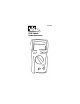
#61-320 320 Series Grade Multimeter
WARNING! 1. DO NOT UNDER ANY CIRCUMSTANCES EXCEED THESE RATINGS: • Voltage is not to exceed 1000 Volts. • Resistance, Capacitance, Logic and Continuity functions are not to be performed on circuits capable of delivering greater than 600 Volts. • Current measurements are not to be performed on circuits capable of delivering greater than 500 Volts 2. To avoid electrical shock hazards and/or damage to the meter: • Do not exceed the voltage ratings for the meter. Use caution when measuring voltage.
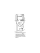
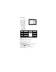
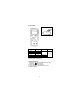
4 3 1 1. Min/Max Switch • Pressing this button once results in the displayed maximum value of the current reading. • Pressing the min/max button once more results in the displayed minimum value of the current reading. • If pressed a third time “Max Min” will flash on the LCD indicating that the minimum and maximum value are being recorded while the current reading is displayed. • Pressing the min/max button for > 2 seconds exits the Min/Max mode.
2. Range Button • Pressing the range button selects the manual ranging mode. • When the range button is pressed RANGE will appear in the upper left of the LCD display. • WHen in the manual range mode, pressing the range button changes the measurement range. • To return to auto ranging, hold the range button for >2 seconds. 3. Hold Button • The hold button is used to hold the measured value for all functions. • The value is displayed alon g with the H annunciator.
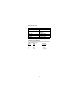
Overload Protection Function VAC & VDC ADC Ohms (Ω) Diode Continuity Overload Protection 1000V µA input: 600V RMS 16A/500V 600VAC/600VDC 600VAC/600VDC 600VAC/600VDC Unit of Measure Multipliers For your reference, the following symbols are often used to make measurement easier: Symbol Verbal Multiplier M mega x 1,000,000 k kilo x 1,000 m milli ÷ 1,000 µ micro ÷ 1,000,000 5
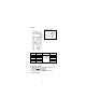
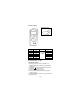
True RMS AC Volt Circuit Connection: Range 600mV 6V 60V 600V 750V Resolution 0.1mV 1mV 10mV 100mV 1V Accuracy Max. Display 600.0 ±(0.9% reading 6.000 + 5 digits) 60.00 600.0 750 AC Conversion Type: Conversions are average sensing RMS calibrated. Input Impedance: 10MΩ less than 100 pF. Frequency Response: 40 Hz ~ 500 Hz To Measure AC Voltage: 1. Plug the black test lead into the COM port and the red test lead into the Hz V Ω µA port. 2. Set the rotary switch to the v˜ position. 3.
DC Volts Circuit Connection: Range 600mV 6V 60V 600V 1000V Resolution 100µV 1mV 10mV 100mV 1V Accuracy Max. Display 600.0 ±(0.5% reading 6.000 + 2 digits) 60.00 600.0 1000 Input Impedance: 10MΩ (over 1000MΩ in 600mV range) To Measure DC Voltage: 1. Plug the black test lead into the COM port and the red test lead into the Hz V Ω µA port. 2. Set the rotary switch to the v position. 3. Connect the meter in parallel with the load or circuit. 4.
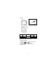
DC Current Circuit Connection: Range Resolution 600µA 6000µA 0.1µA 1µA Accuracy Voltage Max Burden ±(1.0% reading < 4mV / µA 600.0 + 2 digits) 6.000 Overload Protection: µA input: 600V RMS To Measure DC Current: 1. Plug the black test lead into the COM port and the red test lead into the Hz V Ω µA port. 2. Set the rotary switch to the mA or A position. 3. Connect the meter in series with the load or circuit. 4. Measure DC Current.
Frequency/RPM Circuit Connection: Range Resolution 6000Hz 1Hz 60KHz 10Hz 600KHz 100Hz Sensitivity 100mV RMS Accuracy Frequency: 0.01% ±1 digit 6MHz 1KHz 250mV RMS 60MHz 10KHz 1V RMS Overload Protection: 600V rms *Less than 20Hz the sensitivity is 1.5V To Measure Frequency: 1. Plug the black test lead into the COM port and the red test lead into the Hz V Ω µA port. 2. Set the rotary switch to the Hz position. 3. Connect the meter in parallel with the load or circuit. 4. Measure Frequency.
Resistance (Ohms) Circuit Connection: Range 600Ω 6KΩ 60KΩ 600KΩ 6MΩ 60MΩ Resolution Accuracy Max. Display 0.1Ω 600.0 1Ω ±(0.7% reading 6.000 10Ω + 2 digits) 60.00 100Ω 600.0 1KΩ 6.000 10KΩ 60.00 Open Circuit Voltage: -1.3V approx. To Measure Resistance: 1. Turn the power off to the circuit or device that is to be measured and discharge all capacitors before attempting a measurement. 2. Plug the black test lead into the COM port and the red test lead into the Hz V Ω µA port. 3.
Multiplication Guide for Ohms (Ω): 400 = Meter indicates actual resistance 4k = Multiply meter display reading by 1,000 to acquire actual resistance. 40k = Multiply meter display reading by 1,000 to acquire actual resistance. 400k = Multiply meter display reading by 1,000 to acquire actual resistance. 4M = Multiply meter display reading by 1,000,000 to acquire actual resistance 400M = Multiply meter display reading by 1,000,000 to acquire actual resistance.
Determining Resistor Values: To determine the value of a resistor, use the color bands on the resistor and the table on the following page.
Diode Testing Function Resolution Accuracy Max.Test Max.Open Current Circuit Voltage 1mV +(1.5% +5)* 1.5mA 3V * For 0.4V to 0.8V. Overload Protection: 600V rms max Diode Check: To ensure a proper functioning diode, the meter will develop a voltage across the component from a test current. The diode test function allows for measurements of forward voltage drops across diode and transistor junctions. 1. Turn off power to the device or circuit that is being tested and discharge all capacitors. 2.
Capacitance Range 6nF 60nF 600nF 6µF 60µF 600µF 6mF Resolution 1pF 10pF 100pF 1nF 10nF 100nF 1µF Accuracy ±(1.9% rading + 8 digits) Overload Protection: 600V rms To Measure Capacitance: 1. Plug the black test lead into the COM port and the red test lead into the Hz V Ω µA port. 2. Set the rotary switch to the position. 3. Connect the test leads. 4. Measure capacitance.
Continuity Check Circuit Connection: To Verify Continuity: A continuity test ensures that all circuit connections are intact. 1. Plug the black test lead into the COM port and the red test lead into the Hz V Ω µA port. 2. Set the rotary switch to the position. 3. Connect the test leads to the circuit to be measured. The buzzer will sound if the resistance of the circuit measured is lower than 200Ω.
Accessories For AC Current Clamp (61-451): 1. Plug the black test lead of the clamp adapter handle into the COM port and the red test lead into the Hz V Ω µA port. 2. Set the rotary switch to the V˜ position. 3. Press the range button until mV is displayed. Snap the jaw of the current clamp around one of the current carrying conductors.
General Specifications LCD Display: Polarity Indication: 6000 count maximum reading Automatic, negative indicated, positive implied Overrange Indication: “OL” or “-OL” Low Battery Indication: “ ” when the battery voltage drops below operating voltage Size (WxHxD): 82mm x 164mm x 44mm (without holster) Sampling: 1 times/sec LCD Display, Auto Power Off: Approx. 10 min.
Maintenance Warning To avoid electrical shock, remove test lead before opening the cover. Repairs or servicing not covered in this manual should only be performed by qualified personnel. Battery Installation or Replacement: The #61-320 is powered by two 1.5V batteries. 1. Remove the test leads from the front terminals and turn the meter off. 2. Remove the screw from the battery cover and lift to remove. 3. Replace battery. 4.
Fuse Replacement 1. Remove the test leads from the front terminals and turn the meter off. 2. Remove the screw from the battery cover and lift to remove. 3. Remove the screws from the bottom case and the inside of the battery cover and lift the case bottom until it unsnaps from the case top. 4. Remove the defective fuse by gently prying one end of the fuse loose and sliding the fuse out of the fuse holder. 5. Install a new fuse of the same size and rating. Make sure it is centered in the fuse holder. 6.
Lifetime Limited Warranty This meter is warranted to the original purchaser against defects in material or workmanship for the lifetime of the meter. During this warranty period, IDEAL INDUSTRIES, INC. will, at its option, replace or repair the defective unit, subject to verification of the defect or malfunction. This warranty does not apply to defects resulting from abuse, neglect, accident, unauthorized repair, alteration, or unreasonable use of the instrument.