ND 2352-1 61-633 630 Series Ins 12/22/04 #61-633 #61-635 630 Series Technician Grade Multimeter 9:49 AM Page 1
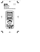
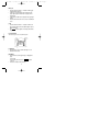
ND 2352-1 61-633 630 Series Ins 12/22/04 1 2 3 4 5 1. LCD Display 2. LCD Menu Function Buttons 3. Function Buttons 4. Rotary Function Switch 5.
ND 2352-1 61-633 630 Series Ins 12/22/04 WARNING! 1. DO NOT UNDER ANY CIRCUMSTANCES EXCEED THESE RATINGS: - Voltage is not to exceed 1000 Volts. - Resistance, Capacitance, Logic and Continuity functions are not to be performed on circuits capable of delivering greater than 600 Volts. - Current measurements are not to be performed on circuits capable of delivering greater than 500 Volts 2. To avoid electrical shock hazards and/or damage to the meter: - Do not exceed the voltage ratings for the meter.
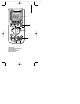
ND 2352-1 61-633 630 Series Ins 1. 2. 3. 4. 5. 6. 7. 8. 9. 10. 11. 12. 13. 14. 15. 16. 17. 18. 19. 20. 21. 22. 23. 24.
ND 2352-1 61-633 630 Series Ins 12/22/04 LCD Menu Function Buttons • Use the Ο button to select the row of the function menu. The rows number is labeled on the right hand side. The active row is marked with a Ο indicator on the left end of the line. • Use the F1, F2, F3 and F4 buttons to select the column of the function menu. The selected menu function will be outlined with a . • The Menu Function Indicator will appear in Recall, Setup, Setting, High or Low modes.
ND 2352-1 61-633 630 Series Ins 12/22/04 Reset • Pressing the F3 button while the Ο indicates row M1 activates the reset function. • The reset button clears all stored data points, and resets the High and low limits, and REF value to the default settings. Auto Hold • Pressing the F4 button while the Ο indicates row M1 activates the auto hold function. • The auto hold function is activated when a stable reading is achieved. • The meter will beep when the meter captures the value in auto hold.
ND 2352-1 61-633 630 Series Ins 12/22/04 High and Low Limit • Pressing the F1 or F2 button while the Ο indicates row M2 activates the high or low limit function. • The high limits may be set by pressing the F1 button and using the +, -, and ➔ buttons to set the values in the secondary display. • The first digit of the high limit value will blink, indicating that it can be changed. • Press the and ➔ buttons to move left and right through the high limit value to select the appropriate digit to be changed.
ND 2352-1 61-633 630 Series Ins 12/22/04 REF (Reference) continued • Press the and ➔ buttons to move left and right through the reference value to select the appropriate digit to be changed. • The + and – buttons will increase or decrease the value of the blinking digit. • The actual measurement will be displayed in the upper right display while in the REF function. • Pressing the F4 button until the will save the reference value and exit the REF function.
ND 2352-1 61-633 630 Series Ins 12/22/04 DBm, dB • Press the F3 button while the Ο indicates row M4 toggles between dBm and dB mode. • In dB mode, the measurement value is displayed in the upper right display, and the dB value is displayed in the main display. • In dBm mode, the dBm load is displayed in the upper right display. • Press and hold the F3 button for 2 seconds to exit dBm/dB mode.
ND 2352-1 61-633 630 Series Ins 12/22/04 Digit Button • The digit button toggles between 40000 or 4000 counts. • The display is updated 2 times per second at 40000 counts and 4 times per second at 4000 counts. Range Button • The range button toggles between auto and manual ranging. • Press the range button for 2 seconds to return to auto range. • When Auto is displayed, the meter is in auto range mode. Ο Button • The Ο button is used to select a row in the menu function.
ND 2352-1 61-633 630 Series Ins 12/22/04 Overload Protection Function VAC & VDC AAC & ADC 10A/500V Ohms (Ω) Diode Continuity Overload Protection 1000V 1A/500V 600VAC/600VDC 600VAC/600VDC 600VAC/600VDC Unit of Measure Multipliers For your reference, the following symbols are often used to make measurement easier: Symbol Verbal Multiplier M mega x 1,000,000 k kilo x 1,000 m milli ÷ 1,000 µ micro ÷ 1,000,000 11 9:49 AM Page 11
ND 2352-1 61-633 630 Series Ins 12/22/04 Voltage Measurements (DC, AC, AC+DC) DC Voltage Range 40mV 400mV 4V 40V 400V 1000V Resolution 1µV 10µV 100µV 1mV 10mV 100mV Accuracy Accuracy (61-633) (61-635) +(0.2% +8) +(0.06% +8) +(0.2% +2) +(0.06% +2) AC Voltage Frequency Resolution Accuracy Accuracy Range Range (61-633) (61-635) 400mV 40 ~ 100Hz 10µV ±(1.2% +5) ±(0.7% +5) 100 ~ 1kHz ±(2.0% +5) ±(1.0% +5) 4V 40 ~ 100Hz 100µV ±(1.0% +5) ±(0.7% +5) 100 ~ 1kHz ±(2.0% +5) ±(1.0% +5) 1k ~ 10kHz ±(3.0% +6) ±(2.
ND 2352-1 61-633 630 Series Ins dBm (typical): 600Ω) dBm (typical): Input Impedance: Overload Protection: AC Conversion Type: AC+DC Volts: Crest Factor: 12/22/04 -15dBm ~ 55dBm (0dBm = 1mW into -80dBV ~ 50dBV = 1VRMS) 10MΩ, <100pF 1000VDC, 750VRMS AC Coupled, True RMS responding Same as ACVRMS +1.00% + 8 digits +1.5% addition error for C.F. from 1.4 ~ 3 +3.0% addition error for C.F. from 3 ~ 4 To Measure Voltage: 1. Plug the Black test lead into the COM port and the Red test lead into the VΩ port. 2.
ND 2352-1 61-633 630 Series Ins 12/22/04 Current Measurements (DC, AC, AC+DC) DC Current Range 40mA 400mA 4A 10A Resolution AC Current Resolution 40mA 400mA 4A 10A 1uA 10uA 100uA 1mA 1uA 10uA 100uA 1mA Voltage Burden: Accuracy (61-633) ±(0.5% +4) Accuracy (61-635) ±(0.2% +4) Accuracy (61-633) ±(1.2% +4) Accuracy (61-635) ±(0.8% +8) 800mV max. for mA input; 1V max. for A input. Input Protection: Equipped with high energy fuse.
ND 2352-1 61-633 630 Series Ins 12/22/04 To Measure Current: 1. Plug the Black test lead into the COM port and the Red test lead into the mA or A port. 2. Set the rotary switch to either the mA or A position. 3. Push the blue button to choose between DC, AC, or AC+DC measurements. 4. Connect the meter in series with the load or circuit. 5. Measure the current. 6. The AC and AC+DC measurements provide a True RMS measurement. 7.
ND 2352-1 61-633 630 Series Ins 12/22/04 Resistance and Low Voltage Resistance Measurements (Ohms) Resistance Range 400Ω 4kΩ 40kΩ 400kΩ 4MΩ 40MΩ Resolution 10mΩ 100mΩ 1Ω 10Ω 100Ω 1kΩ Low Voltage Resistance Range Resolution 4kΩ 100mΩ 40kΩ 1Ω 400kΩ 10Ω 4MΩ 100Ω 40MΩ 1kΩ Accuracy (61-633) ±(0.5% +2) Accuracy 61-635) ±(0.3% +2) ±(0.5% +4) ±(5.0% +5) ±(0.3% +4) ±(5.0% +5) Accuracy (61-633) ±(1.0% +2) Accuracy 61-635) ±(0.6% +2) ±(1.0% +4) ±(7.0% +5) ±(0.6% +4) ±(7.0% +5) • Open circuit voltage: 3.
ND 2352-1 61-633 630 Series Ins 12/22/04 To Measure Resistance: 1. Turn the power off to the circuit or device that is to be measured and discharge all capacitors before attempting a measurement. 2. Plug the Black test lead into the COM port and the Red test lead into the VΩ port. 3. Set the rotary switch to the "Ω & LVΩ Symbols" position. 4. Press the blue button to choose between Ωand LVΩ. • LV setting reduces the maximum test voltage level to about 0.5V to avoid turning on semiconductor devices.
ND 2352-1 61-633 630 Series Ins 12/22/04 Frequency and Duty Factor Measurements Frequency Range 400Hz 4kHz 40kHz 400kHz 4MHz Resolution Duty Factor Resolution 20% ~ 80% 0.1% Sensitivity: Min. frequency: Input protection: Accuracy Accuracy (61-633) (61-635) ±(0.01% +1) ±(0.01% +1) 0.01Hz 0.1Hz 1Hz 10Hz 100Hz Accuracy (61-633) +6 digits Accuracy (61-635) +6 digits 0.5Vp-p for 15Hz ~ 1MHz 1Vp-p for 1 MHz ~ 4MHz 15Hz 600V rms To Measure Frequency: 1.
ND 2352-1 61-633 630 Series Ins 12/22/04 Capacitance Measurements Range Resolution 4nF 40nF 400nF 4µF 40µF 400µF 4mF 10mF 1pF 10pF 100pF 1nF 10nF 100nF 1µF 10µF Accuracy (61-633) ±(1.9% +20) Accuracy (61-635) ±(0.9% +20) ±(2.9% +20) ±(1.9% +20) ±(3.9% +20) ±(2.9% +20) To Measure Capacitance: 1. Turn the power off to the circuit or device that is to be measured and discharge all capacitors before attempting a measurement. 2.
ND 2352-1 61-633 630 Series Ins 12/22/04 Temperature Measurements Temperature Resolution Range -200°C ~ -100°C 0.1°C -100°C ~ -50°C -50°C ~ 1200°C Accuracy Accuracy (61-633) (61-635) N/A 3°C + 1 digit 2°C + 1 digit 1°C + 1 digit To Measure Temperature 1. Plug the temperature probe and adapter into the COM the V port. 2. Set the rotary switch to the °C °F position. 3. For correct reading, ensure that the device being tested contains no voltage. 4.
ND 2352-1 61-633 630 Series Ins 12/22/04 Diode Testing Diode Check: To ensure a proper functioning diode, the meter will develop a voltage across the component from a test current. The diode test function allows measurements of forward voltage drops across diode and transistor junctions. 1. Turn off power to the device or circuit that is being tested and discharge all capacitors. 2. Plug the Black test lead into the COM port and the Red test lead into the VΩ port. 3.
ND 2352-1 61-633 630 Series Ins 12/22/04 Continuity Check To Verify Continuity: A continuity test ensures that all circuit connections are intact. 1. Plug the Black test lead into the COM port and the Red test lead into the VΩ port. 2. Set the rotary switch to the position. 3. Press the blue button until Ω is shown in the display. 4. Connect the test leads to the circuit to be measured. The buzzer will sound if the resistance of the circuit measured is lower than 50Ω.
ND 2352-1 61-633 630 Series Ins 12/22/04 General Specifications Stated accuracies are at 23oC ±5oC at less than 80% RH and without battery indicator displayed.
ND 2352-1 61-633 630 Series Ins 12/22/04 Certifications & Compliances Safety: Designed to IEC 1010-1, UL3111 and CSA Specifications Input Rating: 1000VDC Category II 600VDC Category III 750VAC Category II 600VAC Category III Cat III: Distribution level mains, fixed installations Cat II: Local level mains, appliances, portable equipment Overvoltage Category: Cat I: Signal level, special equipment or parts of equipment, telecommunication, electronics Pollution Degree 2: Do not operate in environments where
ND 2352-1 61-633 630 Series Ins 12/22/04 Battery Installation or Replacement: The #61-633 and #61-635 are powered by one 9 volt battery. 1. Remove the test leads from the front terminals and turn the meter off. 2. Remove the screw from the battery cover and lift to remove. 3. Replace batteries. 4. Make sure the battery box leads do not become pinched between the case and battery cover before replacing the battery cover and screw.
ND 2352-1 61-633 630 Series Ins 12/22/04 Fuse Replacement 1. Remove the test leads from the front terminals and turn the meter off. 2. Remove the screw from the battery cover and lift to remove. 3. Remove the battery. 4. Remove the four screws installed between the top and bottom case. 5. Remove the 4 screws installed between the PCB and top case of the meter, and lift the top case from the PCB. 6.
ND 2352-1 61-633 630 Series Ins 12/22/04 Lifetime Limited Warranty This meter is warranted to the original purchaser against defects in material or workmanship for the lifetime of the meter. During this warranty period, IDEAL INDUSTRIES, INC. will, at its option, replace or repair the defective unit, subject to verification of the defect or malfunction. This warranty does not apply to defects resulting from abuse, neglect, accident, unauthorized repair, alteration, or unreasonable use of the instrument.
ND 2352-1 61-633 630 Series Ins IDEAL INDUSTRIES, INC. Sycamore, IL 60178, U.S.A. 800-304-3578 Customer Assistance www.testersandmeters.