Bender Guide
Features Your IDEAL Bender has engineered features which include: 1. 2. 3. 4. 5. Arrow To be used with stub, offset and outer marks of saddle bends. Rim Notch Locates the center of a saddle bend. Star-Point Indicates the back of a 90° bend. Degree Scale For offsets, saddles and those special situations. A Choice High strength ductile iron or light weight aluminum. The above are features that lead to perfectly predictable and repeatable bends. Instructions Bend conduit with skill and professionalism.
Don’t Forget • When bending on the floor, pin the conduit to the floor. Use heavy foot pressure. • When bending in the air, exert pressure as close to your body as possible. • In case you overbend, use the back pusher or the expanded end of the bender handle to straighten your conduit to fit the job. How to Bend a Stub The stub is the most common bend. Note that your bender is marked with the “take-up” of the arc of the bender shoe. Example: Consider making a 14” stub, using a 3/4” EMT conduit. Step 1.
How to Make Back-To-Back Bends A back-to-back bend produces a “U” shape in a single length of conduit. Use the same technique for a conduit run across the floor or ceiling which turns up or down a wall. Example: Step 1. After the first 90° bend has been made, measure to the point where the back of the second bend is to be, “B”. Step 2. Measure and mark your conduit the same distance, mark “B”. Step 3. Align the mark on the conduit with the Star-Point on the bender and bend to 90°.
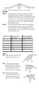
How to make an Offset Bend The offset bend is used when an obstruction requires a change in the conduit’s plane. Before making an offset bend, you must choose the most appropriate angles for the offset. Keep in mind that shallow bends make for easier wire pulling, steeper bends conserve space. You must also consider that the conduit shrinks due to the detour. Remember to ignore the shrink when working away from the obstruction, but be sure to consider it when working into it. Example: Step 1.
Second Bend Example: 30° Bend with a 6” Offset Depth Distance Between Bends ← 12” 1-1/2” → Shrink Amount Reference Table for Offset Bends Degree of Bend 22-1/2° Offset Depth (Inches) 2” 30° 45° 60° 5-1/4” 3/8” 3” 7-3/4” 9/16” 6” 4” 10-1/2” 3/4” 8” 1” 5” 13” 15/16” 10” 1-1/4” 7” 1-7/8” 6” 15-1/2” 1-1/8” 12” 1-1/2” 8-1/2” 2-1/4” 7-1/4” 3” 7” 18-1/4” 1-5/16” 14” 1-3/4” 9-3/4” 2-5/8” 8-3/8” 3-1/2” 8” 20-3/4” 1-1/2” 16” 2” 11-1/4” 3” 9-5/8” 4” 9” 23-1/2” 1-3
Important: Use the same calculation for either set of angles. Example: Step 1. You encounter a 3” O.D. pipe 4 feet from the last coupling. The formula shown in the chart below indicates that for each inch of outside diameter of the obstruction, you must move your center mark ahead 3/16” per inch of obstruction height and make your outer marks 2-1/2” per inch of obstruction height from the center mark. Step 2. The following table gives the actual mark spacings.
CAUTION Be sure to line up all bends to be in the same plane. Hickeys Hickeys require a different approach to bending. It is not a fixed radious device but rather one that requires several movements per bend. The hickey can give you the advantage of producing bends with a very tight radius.